
The glass furnace, as the core equipment in glass production, has a design that directly impacts the quality and performance of glass products. A well-designed glass furnace ensures uniform heating during the processing of glass, reducing the occurrence of defects such as stress and bubbles, thereby improving the product yield and overall quality. By optimizing the structural design of the glass furnace, the efficiency of heat exchange can be enhanced, allowing the abundant thermal energy carried by high-temperature flue gases to be fully utilized, thus reducing energy waste. Therefore, the design of the glass furnace is of paramount importance. This article will inform you about the key areas to focus on when designing a glass furnace.
Throat is an important part of a glass furnace. The melted, clarified, and homogenized glass liquid passes through it into the distribution channel and feed channel for the next homogenization and cooling. Finally, it enters the forming equipment for production molding. Every day through this narrow channel there is 360~400t glass liquid, so the glass liquid is very big scouring and wear and tear, and the throat located in the working environment is terrible, the surrounding temperature is high, once there is a problem can‘t be replaced.
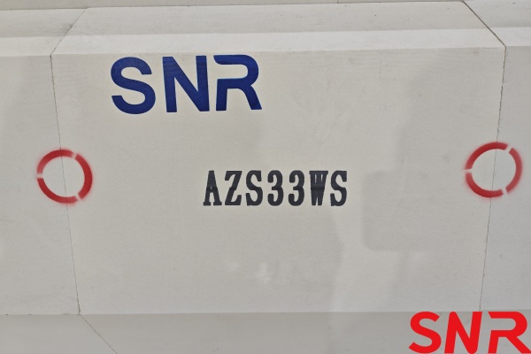
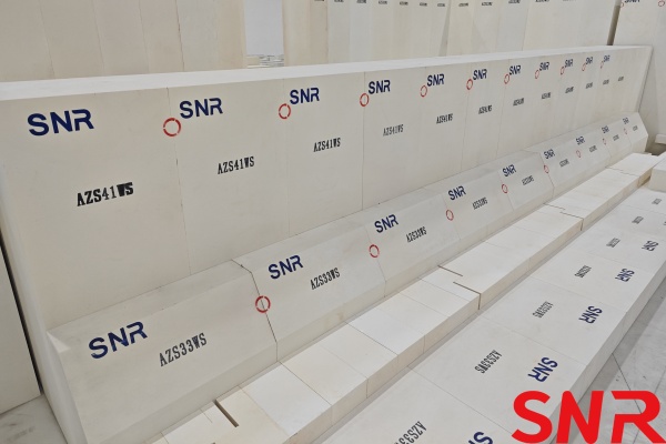
Therefore, the throat chooses a better anti-erosion performance of fused cast AZS41 # block. Fused cast AZS block has an upward erosion hole performance at the interface of the solid phase, liquid phase, and gas phase. Fused cast AZS block is the solid phase, the glass liquid is the liquid phase, and the gas bubbles remaining in the glass liquid are the gas phase. Throat cover block erosion than other places is larger, 5~6 years on the upward erosion off 300~400mm thickness. After the erosion of 300~400mm, the feeding depth of the liquid glass will become shallower, which is equivalent to the depth of the original melting end of the glass furnace has been reduced by 300~400mm, and the output of the glass furnace will certainly be greatly affected.
To ensure the discharge volume, the temperature inside the glass furnace can only be increased, which then leads to an increase in energy consumption. After a few years, the glass furnace cover blocks and other parts of the glass furnace burn out, the glass furnace becomes thinner, the internal temperature increases, and the heat dissipation from the glass furnace further increases.
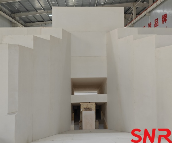
In summary, the structure of the throat affects the life of the glass furnace, the amount of material discharged, and the energy consumption. According to the mechanism of erosion of throat cover blocks, we designed the contact surface between the throat cover blocks and the glass liquid to be inclined. The bubbles in the glass liquid do not easily adhere to the throat cover blocks, thereby greatly slowing down the erosion of the throat cover blocks and extending the life of the throat and the glass furnace.
2. BOTTOM OF THE GLASS FURNACE
The structure of the bottom in the glass furnace is also prone to affect the life of the glass furnace, especially the high white material or crystal white material glass furnace. Because of its good heat permeability, the bottom of the glass furnace temperature is high, and the material will inevitably bring in some metal. Metallic substances on the fused cast AZS block erosion are more powerful (downward erosion holes). Once the fused cast AZS block is etched through, the glass liquid penetrates to the bottom of the slab below, it will produce ‘upward erosion holes‘. Once the formation of stalactites erosion, the fused cast AZS block will soon corrode, thus causing great harm to the entire bottom of the safety of the bottom in glass furnace, affecting the life of the glass furnace, and in serious cases even leakage accident.
To prevent the occurrence of such events, one is to strictly control the entry of the metal in the matching material, and the second is to strengthen the bottom leakage prevention structure. The design of the bottom structure of the glass furnace is a multi-layer composite structure.

3. MELTING END
3.1 Length and width of the melting end
Once the melting rate is determined, then the melting area of the glass furnace can be determined. We assume that the melting area of the glass furnace is 152t/m2. In designing the length and width of the melting end, we adhere to the design concept that when considering the flame coverage, not only consider the flame width but also pay more attention to the length of the flame. In the design, we draw on the principle of float glass furnace, i.e., to separate the 5 stages of glass melting:
►Silicate reaction
►Glass formation
►Homogenization of glass
►Clarification of glass
►Cooling of the glass
These 5 melting stages take place in different spaces and at the same time. Thus, we believe that when designing an end-fired glass furnace, as long as the flame can reach the length, choose to have a large aspect ratio, so that the clarification and homogenization of the glass liquid has a certain area. In other words, the absolute length of the glass furnace should be large as far as the flame can reach.
3.2 Depth of the melting end
At present, in the more advanced glass furnaces, melting ends are divided into shallow melting ends and deep melting ends. To strengthen the hot spot and improve the quality and production of glass, the glass furnace is usually equipped with a weir. We design the front of the weir as a shallow melting end and the back of the weir as a deep melting end. In front of the weir is the melting zone (also known as the initial melting zone). The surface of the liquid glass in the melting zone is covered with a thick layer of compound and the foam formed in the process of decomposition of the compound melting, which is the bad conductor of heat and a layer of thermal insulation. Because the insulation layer affects the heat penetration and transfer, the depth of the shallow melting end should not be too deep. If it is too deep will form a thick immobile layer or slow-moving layer at the bottom of the glass furnace, the thickness of this immobile layer or slow-moving layer will change with the temperature change at the bottom of the glass furnace or the change in the amount of material discharged, which will be added to the natural convection of the glass liquid, thus affecting the quality of the glass liquid; And these immobile or slow-moving layers of vitreous liquid added to the natural convection of the vitreous liquid will cause repeated heating of the vitreous liquid, increasing energy consumption.
4. WEIR
Behind the weir for the clarification and homogenization area is also called the fine melting area (referred to as the deep clarification zone), we should deepen the depth of the clarification zone in this area. Deep clarifiers to improve the quality of glass furnaces, yield, and reduce energy consumption are very obvious.
A deep clarifier increases the volume of the glass furnace and extends the residence time of the glass liquor in the furnace;
The glass clarification process is the process of removing visible air bubbles.
Formally, this process is a simple hydrodynamic process, but it is a complex physicochemical process. The clarification rate of the glass liquid the viscosity of the glass liquid, the viscosity of the glass liquid, and the temperature of the glass liquid. If the depth of the deep clarifier is too deep, although the bubble by the static pressure of the glass liquid is larger, but because the glass liquid temperature is low, resulting in the viscosity of the glass liquid being large, the bubble discharge is difficult.
According to the computer simulation technology, the temperature of the glass liquid at the bottom of the deep clarifier should be not less than 1300℃. Therefore, the depth of the deep clarifier of this glass furnace is designed as 2200mm. When designing and calculating the depth of the deep clarifier of the melting end, not only the heat permeability of glass should be considered, but also the size of the glass furnace. For the same kind of glass, a large glass furnace can be appropriate to add a deep clarifier.
5. FEEDING TANK
5.1 Structure of the feeding tank
The distribution of the mating material in the melting bath plays a very important role in the melting rate of the mating material. The wider the doghouse, the wider the feeder machine should be. In the case of the same feeder volume, the thinner the thickness, the higher the heat utilization and the faster the melt of the compound. Because of the large amount of material output from this glass furnace, single-sided feeding can reduce heat radiation and high-temperature airflow loss of liquid flow. However, considering the long-term operation, the feeding machine and other materials with the material transport system wear and tear, inevitably out of trouble, to ensure that the normal in and out of the material has a certain degree of difficulty. Therefore, the symmetrical bilateral feeding tank structure should be used. We design the feeding tank with the concept of lengthening the feeding tank. It makes the compound material in the pre-melting end carry on the relatively full silicate reaction, the surface of the compound material in the glass furnace has already begun to carry on the silicate reaction, the surface has become viscous, the flame airflow is not easy to the surface of the compound material of the fine powder blowing up, It can reduce clogging of the latticework of the heat storage chamber, reduces dust flying and thus reduces the erosion of the glass furnace itself and extends the life of the glass furnace.
5.2 Shape of the feeding tank
The shape of the feeding tank should be determined by the type of feeding machine. Practice at home and abroad has proved that the feeding effect and energy-saving effect of the swing wrap-in feeding machine is the best at present, and it can save energy by about 5%. The principle of energy saving of the swing wrap-in charging machine is as follows:
Generally, the mating material added into the glass furnace by the feeding machine floats on the surface of the glass liquid. Because the mixture is loose, its thermal conductivity is very low, the melting speed is slow. The user is wrapped into the feeding machine, with the material to the glass liquid extrusion, in the process, the high temperature of the glass liquid is squeezed up to fill the material with the air holes, increasing the thermal conductivity of the material. If the feeding machine is installed and adjusted properly, with the material as a wrapped dough, partially wrapped in the glass liquid, thus greatly accelerating the melting speed, melting fast output can be increased, and thus reduce energy consumption.
Oscillating wrapped into the feeding machine can be left, middle, and right 3-direction oscillating feeding, the number of times the 3 directions push the material can be arbitrarily set to adjust so that the pile of material in the melting end distribution is very uniform, the melting end area can be fully utilized, it effectively use the flame space radiation energy, improve the utilization rate of the melting end, and thus further accelerate the speed of the melting.
Due to the separate feeding in three directions, the compound is surrounded by the glass liquid in a small pile in the glass furnace, which increases the contact area with the glass liquid and realizes the thin-layer feeding.
From another point of view, the swing-in feeding also has the advantage of prolonging the life of the glass furnace. As the swing-in feeding pushes the mating material in three directions at regular intervals, the mating material is uniformly distributed at the back end of the melting end, and it has a short time of direct contact with the sidewall blocks, or even no direct contact with them, which prolongs the life of the sidewall blocks, as the erosion of the mating material on the sidewall blocks is much bigger than that of glass liquids.
Conclusion
Optimizing glass furnace design requires meticulous attention to material selection, structural geometry, and thermal dynamics. Key areas—throat, bottom, melting end, weir, and feeding system—demand tailored solutions to balance longevity, energy efficiency, and product quality. As a leader in fused cast AZS refractory materials, HENAN SNR REFRACTORY CO.,LTD offers comprehensive solutions for furnace design, construction, and upgrades.
CONTACT: zoe@snrefractory.com
WEBSITE: www.snr-azs.com
 info@snr-azs.com
 +86-18203976036