
The glass furnace, as the core equipment for glass production, has insulation performance that directly relates to multiple critical aspects including energy consumption costs, glass furnace lifespan, product quality, working environment, and environmental compliance. As a high energy-consuming industry, fuel costs account for 30%-50% of glass production expenses. Poor insulation can lead to 20%-40% heat loss, causing a substantial increase in fuel consumption, while proper insulation can control heat loss within 10%. For a single glass furnace with a daily melting capacity of 500 tons, this can save millions of yuan in fuel costs annually. Simultaneously, insufficient insulation will exacerbate temperature fluctuations in the furnace body, causing refractory materials to age faster due to thermal shock and chemical erosion, shortening the glass furnace lifespan from 5-8 years to 8-12 years, and reducing major repair costs by tens of millions of yuan.
In terms of product quality, poor insulation can cause uneven temperatures within the glass furnace, leading to defects such as stones, bubbles, and streaks, reducing the qualified rate, whereas proper insulation can maintain temperature stability within ±5°C in all zones, improving the qualified rate from 85% to over 95%. Additionally, poor insulation performance increases fuel consumption, leading to higher emissions of pollutants such as carbon dioxide, which is detrimental to environmental compliance. Good insulation can reduce pollutant emissions, helping enterprises meet the "dual-carbon" policy and local environmental requirements. This article systematically introduces the selection standards, key construction technologies, and quality control requirements for insulation materials in glass furnace bottoms and sidewalls, providing professional guidance for glass furnace design and construction.
1. Selection Standards for Glass Furnace Refractory Materials
2. Key Technologies for Sidewall and Bottom Insulation
3. Combined Cold and Hot State Insulation Construction Technology for the Crown
4. Detailed Insulation System Construction Technology
5. Construction Quality Control Requirements
6. Common Problems and Solutions
1. Selection Standards for Glass Furnace Refractory Materials
1.1 The Core Position of Fused Cast AZS Refractory Blocks
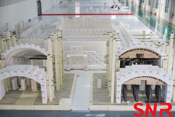
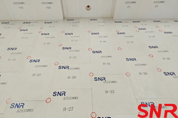
Fused zirconia corundum bricks (Fused cast AZS block), due to their excellent resistance to glass liquid erosion, have become the preferred material for modern glass furnace sidewalls and bottoms:
Chemical Composition Advantages:
Al₂O₃ (aluminum oxide): provides high refractoriness (melting point 2050℃) and good mechanical strength, and is the main element of the fused cast AZS block.
ZrO₂ (zirconium oxide):
► Anti-glass erosion: ZrO₂ has extremely strong chemical stability at high temperatures, especially resistant to erosion by alkaline glass melts.
► Phase change toughening: ZrO₂ has a transformation between the monoclinic phase and the tetragonal phase at room temperature, which can absorb stress and improve the thermal shock resistance of the fused cast AZS block.
SiO₂ (silicon dioxide): forms a eutectic phase (mullite) with Al₂O₃, improving sinter ability and structural density.
Physical Properties:
Bulk density ≥3.45g/cm³, apparent porosity ≤1.5%. High density and low porosity can effectively prevent glass liquid penetration.
|
Typical physical properties comparison table (taking AZS-33 as an example) |
||
|
Performance Indicators |
Typical value range |
Comparative material (high alumina brick) |
|
Bulk density(g/cm3) |
3.45~3.75 |
2.8~3.2 |
|
Apparent porosity (%) |
<1.5 |
15~20 |
|
Cold Crushing Strength (Mpa) |
200~300 |
50~100 |
|
Softening temperature under load (℃) |
≥1700 |
1500~1600 |
|
Thermal expansion coefficient (/℃) |
7.5×10⁻⁶(20~1500℃) |
8.0×10⁻⁶ |
Thermal Stability:
Thermal expansion coefficient (20-1000°C) ≤7.5×10⁻⁶/°C, ensuring that excessive stress is not generated during drastic temperature changes.
Microstructure advantages
► Eutectoid structure: Al₂O₃ and ZrO₂ form a eutectic network, and ZrO₂ particles are evenly distributed in the corundum matrix to form an "island structure" to hinder crack propagation.
► Glass phase distribution: A small amount of SiO₂ forms a glass phase to fill the grain boundary and increase the density, but the content needs to be controlled (about 10-15%) to avoid high temperature softening.
1.2 Principles for Selecting Insulation Materials
|
Component |
Working Layer Material |
Insulation Layer Material |
Temperature Range (°C) |
Material Property Requirements |
|
Glass Furnace Bottom |
AZS-33/41 |
Alumina hollow sphere bricks + calcium silicate boards |
1300-1650 °C |
Excellent high-temperature stability, compressive strength ≥8MPa, thermal conductivity ≤0.25W/(m·K) |
|
Side Wall |
AZS-36/41 |
Lightweight high-alumina bricks + nano-porous insulation boards |
1400-1700 °C |
Good thermal shock resistance, flexural strength ≥5MPa, thermal conductivity ≤0.18W/(m·K) |
|
Crown |
Silica bricks or fused Cast AZS blocks |
Lightweight high-alumina bricks (Al₂O₃ content 50-65%), mullite bricks or ceramic fiber modules |
1500-1600 °C |
High temperature resistance, erosion resistance, ultra-low thermal conductivity |
When selecting insulation materials, the following key factors need to be considered:
1) Temperature Gradient Matching: From the hot face to the cold face, the maximum service temperature of materials in each layer should decrease progressively to form a reasonable temperature gradient.
2) Thermal Expansion Compatibility: The thermal expansion coefficients of materials in adjacent layers should be as close as possible to avoid structural cracking caused by differences in thermal expansion.
3) Chemical Compatibility: Ensure that materials in adjacent layers will not undergo harmful chemical reactions at high temperatures.
4) Construction Feasibility: Material dimensions, weight and other physical characteristics should be suitable for on-site construction conditions.
2. Key Technologies for Sidewall and Bottom Insulation
2.1 Analysis of Main Heat Loss Pathways
In glass furnaces, the bottom accounts for about 25-35% of total heat loss, while the sidewalls account for about 15-25%. The main heat transfer mechanisms include:
► Conductive Heat Loss: Heat transfer through refractory materials to the steel structure. Research shows that optimized insulation structures can reduce conductive heat loss by more than 30%.
► Radiative Heat Loss: Radiation from high-temperature surfaces to the environment. The use of low-emissivity surface coatings can effectively reduce this type of loss.
► Convective Heat Loss: Air convection around the glass furnace surface. Improving the surface temperature distribution of the furnace body can significantly reduce convective losses.
Example of Heat Loss Calculation:
For a float glass furnace with daily production of 200 tons, the bottom area is about 150m² and the sidewall area is about 80m². Before optimization, the heat flux density of the bottom is about 450W/m² and the sidewall is about 550W/m², with annual heat loss equivalent to about 1200 tons of standard coal. After adopting optimized insulation technology, energy savings of 15-20% can be achieved, equivalent to saving 180-240 tons of standard coal annually.
2.2 Core Parameters for Insulation Design
|
Parameter |
Bottom Requirements |
Sidewall Requirements |
Testing Method |
Influencing Factors |
|
External Surface Temperature |
≤80°C |
≤100°C |
Infrared thermometry |
Insulation layer thickness, material thermal conductivity, ambient temperature |
|
Heat Flux Density |
≤350W/m² |
≤450W/m² |
Heat flux meter measurement |
Temperature gradient, material properties, structural integrity |
|
Heat Loss |
≤5% of total energy consumption |
≤3% of total energy consumption |
Heat balance calculation |
Furnace design, operating parameters, insulation effectiveness |
Technical Explanation: Because the sidewalls are in direct contact with high-temperature glass liquid, gradient insulation design is typically adopted while ensuring structural stability, with thermal conductivity decreasing layer by layer from the hot face to the cold face. A typical gradient insulation structure includes:
1) Contact Layer: Direct contact with glass liquid, using fused cast AZS blocks with thickness of 200-300mm
2) Transition Layer: Lightweight high-alumina bricks with thickness of 100-150mm
3) Insulation Layer: Nano-porous insulation boards with thickness of 80-120mm
4) Sealing Layer: High-temperature sealant coating with thickness of 2-3mm
3. Combined Cold and Hot State Insulation Construction Technology for the Crown
3.1 Defects of Hot State Insulation
Currently, most domestic glass factories use hot state insulation for glass furnace crowns. The purpose is to avoid damage to the insulation layer structure caused by thermal expansion during the heating process. This approach is normal when insulation technology is not yet mature. However, this insulation method has significant defects.
► First is high labor intensity. When the glass melting furnace reaches normal production temperature, the temperature on the crown is extremely high. The insulation materials used generally contain a certain amount of phosphate, which emits strong irritating odors when volatilized at high temperatures, causing certain harm to human body. Construction under such harsh conditions requires tremendous physical effort, and in severe cases can cause headaches, nausea or even fainting.
► Second is long construction time. Generally, hot state insulation for a glass melting furnace with daily capacity of 400-500 tons requires about 40 days.
► Finally, the quality of such insulated crowns is often unsatisfactory. In later stages, phenomena such as crown "reddening" (where a local area of the crown is eroded to form a large melting cavity without perforation, appearing like a lantern emitting orange-red light) or even brick dropping often occur. This not only greatly shortens the service life of the glass melting furnace, but also seriously affects the quality of glass products.
The main reasons are: First, hot state insulation often does not pay special attention to the cold state construction quality of the crown, especially the problem of imperfect mortar joints; Second, during heating up glass furnace, because of large temperature differences inside and outside the crown body, it is generally difficult to achieve uniform expansion, resulting in large crown deformation and many cracks after reaching operating temperature; Third, due to harsh working conditions, hot state insulation construction is difficult to perform carefully, resulting in relatively rough construction quality.
3.2 Improvements with Combined Cold and Hot State Insulation Construction Technology
The combined cold and hot state insulation construction technology can greatly overcome various defects caused by the above insulation methods, thereby making the quality of insulated crowns more perfect. This insulation construction technology is called combined cold and hot state because most construction is completed in cold state, with only a small part of work done in hot state. This is because these materials currently cannot adapt to thermal expansion changes of the glass melting furnace in hot state. Below is a brief introduction to this insulation construction technology.
1) Must select high-quality, reliable insulation-specific refractory materials. In addition to using high-quality silica bricks for crown bricks, it is more important to select high-quality silica mortar for crown construction and silica-based sealants, plastics and ramming mixes for insulation. These materials must not only have specified high-temperature erosion resistance, but also must have thermal expansion properties matching the crown expansion, otherwise the insulation layer quality cannot be guaranteed.
2) Crown construction must strictly control construction quality. During construction, crown bricks must not be inverted, chipped or broken. Especially mortar joints must be uniform and tight without any carelessness. This is crucial for the final quality of the crown and insulation layer, yet is often overlooked by many people.
Once there are voids in crown brick joints, given suitable conditions, "rat hole" erosion can easily occur. The reason is that silica bricks have poor resistance to R₂O liquid phase. The R₂O liquid phase first erodes the binder in the bricks - this weak link, causing binder loss, which then leads to aggregate loosening and falling off. This vicious cycle causes the erosion area to grow larger and larger, eventually forming rat holes until brick dropping occurs. Some believe that before insulation when the crown is heated to operating temperature, using ultra-fine silica powder to reprocess larger brick joints formed by careless construction and secondary cracks formed after heating (the purpose is to fill these brick joints), and then applying a layer of strong and erosion-resistant silica-based sealant on the outer surface of the crown can avoid rat hole erosion. In fact, this view is incomplete. Applying a layer of silica-based sealant can play a certain role, but this is limited. And injecting ultra-fine silica powder hardly works. The key here is the size and location of brick joints. When brick joints are very small, applying a layer of silica-based sealant is effective. When brick joints are relatively large and through holes, neither injecting ultra-fine silica powder nor applying a layer of silica-based sealant will help. Once such brick joints appear, injecting ultra-fine silica powder will obviously leak into the glass furnace. And simply applying a layer of silica-based sealant, since relatively large brick joints already exist, if they happen to be located before the hot spot (where R₂O gas concentration is relatively high in this area of the furnace), rat hole erosion can easily form.
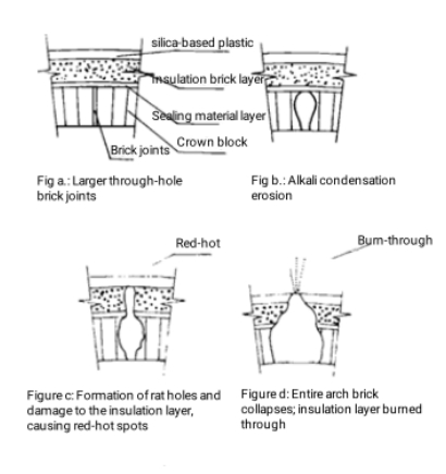
The so-called relatively large brick joints are relative - they are very small relative to the entire large glass furnace, see Figure a. For such brick joints, R₂O gas in the glass furnace gas can easily enter them. Because the temperature inside brick joints is relatively low, it will condense into liquid at about 1400°C, and this high-concentration R₂O liquid will quickly erode silica bricks to form rat holes, see Figure b. Once rat holes grow to a certain size, high-temperature flame gas in the glass furnace will burn through the insulation layer causing reddening or even flame penetration, see Figure c, d. Because the insulation layer is generally relatively thick, plus the stronger sealant and plastic layers, when this phenomenon occurs and the insulation layer at the reddening/penetration area is removed, a large hole is often found in the crown, or even several crown bricks have already dropped.
If there are a few tiny brick joints occasionally, the air in them cannot circulate due to the siliceous sealing material layer, so it is difficult for the R2O gas in the glass furnace to enter or the amount of R2O gas entering is very small, which is not enough to form R2O liquid, and thus does not erode the silica bricks. In addition to paying special attention to the cold masonry quality of the crown to prevent the appearance of empty brick joints, the insulation construction technology also has a large amount of insulation construction work completed in the cold state, so that the temperature difference between the inside and outside of the silica brick arch is small when the glass furnace is heated. In addition, the insulation materials used can expand synchronously with the silica brick arch and the special glass furnace baking technology, so there will be no secondary arch cracks caused by glass furnace baking, and naturally the problem of rat hole erosion is completely eliminated. This is the unique and distinctive key to the cold and hot state combined insulation technology.
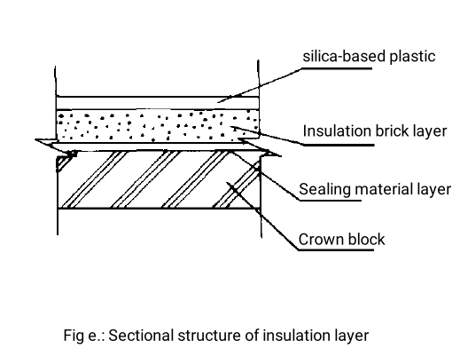
3) Implement cold state insulation construction. After crown construction is completed, clean its surface and evenly apply a layer of silica-based sealant, then build insulation bricks, see Figure e. To avoid damage to the insulation layer caused by expansion, certain expansion joints need to be reserved in the insulation layer.
4) Careful heating. Since most insulation layer structures of combined cold and hot state insulation technology have been completed in cold state, and to completely avoid secondary cracks in the crown during heating, the crown must expand absolutely uniformly during heating without any bulging or unnecessary cracks. This is also a very critical part of this technology. From the theory behind heating to the development of heating curves and process parameters, operating procedures, to the selection and arrangement of heating equipment, a complete set of mature technology must be guaranteed.
5) Perform hot state insulation finishing construction. After heating to operating temperature, fill the expansion joints reserved during cold state insulation construction, including all expansion joints in the silica brick crown with bricks and level them. To avoid damage caused by expansion, this work must also be done in sections. Silica bricks used for filling expansion joints must be preheated. In addition, to enhance insulation effect and facilitate crown cleaning during normal production, a layer of relatively smooth silica-based plastic is finally applied outside the insulation layer, see Figure e.
4. Detailed Insulation System Construction Technology
4.1 Multi-layer Bottom Construction Process
Typical five-layer construction sequence:
1) Foundation treatment
The concrete foundation needs to be fully cured (usually more than 28 days), and the surface flatness error should not exceed 3mm/m. If the foundation is not flat, high temperature may cause uneven force on the bottom of the melting tank and cause cracking. It is usually necessary to apply asphalt or lay a layer of ceramic fiber blanket on the concrete surface to buffer the thermal expansion stress during the heating process of the glass furnace. If a steel structure is used for support, the welding quality needs to be checked and anti-rust treatment needs to be performed to ensure that the load-bearing capacity meets the design requirements.
2) Insulation layer construction
The function of the insulation layer is to reduce heat loss downward and reduce energy consumption. Commonly used insulation materials include calcium silicate board (for areas below 800℃) and alumina hollow ball bricks (for high temperature areas). During construction, staggered paving is required, and the brick joints are controlled within 1mm, and special high-temperature glue is used for bonding. If the design is a multi-layer insulation structure, the joints of each layer must be staggered to avoid the formation of a thermal bridge effect. The compressive strength of the insulation material must meet the load requirements of the upper refractory material, otherwise the insulation performance may decrease due to compression deformation after long-term use.
3) Construction of anti-seepage layer
The anti-seepage layer is located above the insulation layer. Its main function is to prevent glass liquid or molten material from penetrating into the insulation layer and causing structural damage. Commonly used materials are clay sealants or zircon mortar. They need to be evenly applied during construction. The thickness is usually 10~20mm, and compacted with a spatula to ensure that there are no bubbles or cracks. After the application is completed, it needs to be naturally dried for more than 48 hours. If necessary, it can be baked at low temperature (about 200℃) to enhance the compactness. If cracks or peeling occurs in the anti-seepage layer, it must be repaired before subsequent construction.
4) Masonry of refractory layer
The refractory layer is the core part of the melting tank bottom and is in direct contact with high-temperature glass liquid. Therefore, it has extremely high requirements for material performance and masonry accuracy. The lower layer usually uses bonded AZS blocks or fused mullite bricks. The brick joints should not exceed 1.5mm during masonry, and high-alumina fire clay matching the brick material composition should be used. The upper layer uses fused cast AZS blocks because of their excellent corrosion resistance. Before laying, it is necessary to pre-layout according to the design drawings to ensure the accurate position of the blocks. The block joints must be controlled within 0.5mm, and the block surface must be ground to ensure flatness when necessary. The staggered lock joint structure is used during masonry to enhance the overall stability. The reservation of expansion joints is very important, usually 5~8mm per meter, filled with ceramic fiber or compressible cardboard to avoid thermal expansion and cracking of the block body.
5) Sealing layer construction
After the refractory layer is completed, high-temperature sealing materials (such as phosphate-bonded cement or zirconium coating) need to be applied on the surface to cover all brick joints to prevent glass liquid from penetrating. The thickness of the sealing layer is usually 2~3mm, and it can be scraped or sprayed. After construction, it needs to be dried naturally and slowly heated in the oven stage (usually baked at a temperature below 300℃ for 24 hours) to ensure that the sealing layer is cured without cracking.
4.2 Composite Sidewall Insulation Construction Key Points
► Staggered Joint Construction: Fused cast AZS block adopt "herringbone" laying method with vertical joints staggered ≥50mm. Pause for 2 hours after every 1m height to allow initial mortar setting.
► Expansion Control: Reserve expansion joints of 3-5mm/m, filled with ceramic fiber paper. Expansion joints should avoid key stress areas.
► Anchoring System: Arrange 9-12 ceramic anchors per square meter, temperature resistance ≥1300°C. Anchor installation angle should be 45°±5°.
► Air Tightness Treatment: Brush high-temperature sealant on outer surface with thickness ≥2mm. The coating should be applied in two passes with 4-6 hours interval.
Construction Precautions:
1) Construction environment temperature should be maintained between 5-35°C, humidity ≤70%. Insulation measures need to be taken during winter construction.
2) All refractory materials should be placed in the construction environment for more than 24 hours before construction to adapt to ambient temperature and humidity.
3) It is strictly forbidden to moisten the blocks with water during the masonry process to avoid affecting the performance of the refractory mud.
4) After completing each construction section, immediately conduct quality inspection and record results.
5. Construction Quality Control Requirements
5.1 Material Incoming Inspection Standards
|
Material Type |
AZS Blocks |
Insulation Boards |
Refractory Mortar |
Ceramic Anchors |
|
Inspection Items |
ZrO₂ content, bulk density |
Thermal conductivity (800°C) |
Bond strength |
Tensile strength, temperature resistance |
|
Qualification Standards |
≥33%, ≥3.75g/cm³ |
≤0.15W/(m·K) |
≥5MPa (1400°C) |
≥8MPa, ≥1300°C |
|
Sampling Ratio |
5% per batch |
3 tests per 100m² |
1 test per ton |
5 tests per 500 pieces |
5.2 Key Control Points During Construction
► Environment Control: Construction environment temperature 5-35°C, humidity ≤70%. Special measures required if beyond this range.
► Dimensional Tolerances: Bottom flatness ≤2mm/m, sidewall verticality ≤3mm/2m. Use laser level for inspection.
► Joint Treatment: Brick joint filling ≥95%, inspected with special gauges. Critical areas require X-ray inspection.
► Curing Regime: Castable require ≥24h curing, heating rate ≤15°C/h. Maintain humidity ≥80% during curing.
5.3 Acceptance Testing Items
1) Air Tightness Test: 0.5kPa pressure test, leakage rate ≤1%/h. Test duration at least 2 hours.
2) Thermal Imaging Inspection: Inspect outer surface temperature distribution uniformity. Areas with temperature difference exceeding 20°C require focused inspection.
3) Heat Balance Test: Deviation between actual heat loss and design value ≤10%. Test should be conducted after glass furnace operates stably for 72 hours.
4) Structural Strength Test: Conduct non-destructive testing on critical areas to ensure structural integrity.
6. Common Problems and Solutions
During the material acceptance process, strict quality control standards must be enforced, with professional testing conducted on key performance indicators for different materials. For fused cast AZS blocks, the focus is on testing zirconium oxide (ZrO₂) content (typically required to be ≥33%), bulk density (standard value 3.4-3.6 g/cm³), and surface quality (including defects such as cracks and pores). Insulation materials require testing for thermal conductivity (required ≤0.2 W/(m·K)), compressive strength (≥0.5 MPa), and thermal stability. Refractory mortar must be tested for bonding strength (≥1.5 MPa), chemical composition (Al₂O₃ content ≥65%), and workability. Ceramic anchors, on the other hand, must be inspected for tensile strength (≥15 MPa), high-temperature resistance (≥1300°C), and dimensional tolerance (±0.5 mm).

During construction, special attention must be paid to common quality issues.
1) Cracking in the sidewall blocks: The root cause is often inaccurate calculations or construction deviations in the expansion joint dimensions. Solutions include using infrared thermal imaging to locate cracked areas, employing diamond cutting tools to create new expansion joints (5-8 mm wide), and filling them with high-purity ceramic fiber wool (ZrO₂ content ≥95%). Additionally, during the design phase, finite element thermal stress analysis software must be used to precisely calculate thermal expansion, and laser positioning instruments should be employed during construction to ensure expansion joint placement accuracy (±1 mm).
2) Condensation on the outer surface: This typically indicates defects in the insulation system, such as insufficient insulation thickness or thermal bridging. Solutions include revisiting thermal calculations, using dew point analyzers to determine the minimum required insulation thickness, and selecting nano-aerogel composite materials (thermal conductivity ≤0.018 W/(m·K)) as additional insulation layers. During construction, special attention must be paid to ensuring that the load of the added insulation layer remains within the steel structure‘s bearing capacity (≤150 kg/m²). Joints should be staggered and sealed with high-temperature sealant.
3) Anchor failure: The main causes include material creep at high temperatures (below 1300°C operating temperature), installation angle deviations (>5°), or insufficient thermal expansion compensation. The solution involves selecting alumina-zirconia composite ceramic anchors (Al₂O₃ ≥85%, ZrO₂ ≥13%), using torque wrenches to control tightening force (15-20 N·m) during installation, and leaving 3-5 mm expansion gaps around the anchors. It is recommended to regularly inspect anchor conditions using industrial endoscopes and establish preventive maintenance records.
After implementing all corrective measures, a 72-hour thermal test (simulating operational temperatures) must be conducted. Comprehensive acceptance testing should be performed using equipment such as infrared thermal imagers and ultrasonic thickness gauges to ensure all indicators meet design requirements. Additionally, it is advisable to establish a digital operation and maintenance system for real-time monitoring and trend analysis of key parameters to achieve predictive maintenance.
Expert Recommendations:
1) It is recommended to inspect fused cast AZS block erosion at glass furnace bottom every 2 years using endoscope. When residual thickness is less than 50% of original thickness, replacement should be planned.
2) For daily maintenance, sidewall temperature monitoring point density should be ≥2 points/m², which can be increased to 4 points/m² for critical areas.
3) Establish glass furnace insulation system archives, recording each maintenance situation and material performance changes.
4) Operator training should include insulation system maintenance knowledge to ensure timely discovery and resolution of problems.
Future Outlook
With the advancement of "dual-carbon" goals, glass furnace insulation technology is developing toward ultra-low thermal conductivity, intelligent regulation, and full lifecycle management. Through comprehensive application of new materials, new structures and intelligent control, it is expected to further reduce energy consumption of existing furnaces by 15-20% and CO₂ emissions by more than 25%. Meanwhile, the introduction of digital twin technology will enable virtual commissioning and optimization of furnace insulation systems, greatly improving design efficiency and operational reliability.
Henan SNR Refractory Co., Ltd. is dedicated to the manufacture, research and development of fused cast AZS refractory materials and bonded refractory materials for the glass industry. Meanwhile, SNR can provide total solutions and services for glass furnace design, glass furnace construction, renovation, and upgrading. Please contact me if you have any requirements.

CONTACT: zoe@snrefractory.com/WhatsApp:+86 18172389584
 info@snr-azs.com
 +86-18203976036