Glass electric melting technology is a clean, efficient and advanced technology that can be used to produce different types of glass. Its principle is to apply electrical energy to molten glass to generate Joule heat for further melting. Since the world‘s first all-electric melting furnace was put into production in the UK in 1956, this technology has made great progress. At present, electric furnaces have a variety of structural forms. This work focuses on the characteristics and applications of cold top vertical melting furnaces (i.e. CTVM furnaces).
1.Characteristics of CTVM furnaces
1.1 Vertical Melting
1.2 Cold top layer
1.3 Flexible arrangement of electrodes
1.4 Fully covered automatic charging
1.5 Simple melting process
1.6 Wide range of cullet addition
1.7 High melting efficiency
1.8 Simple furnace auxiliary configuration
2.How to choose refractory bricks for CTVM furnaces
1.Characteristics of CTVM furnaces
1.1 Vertical Melting
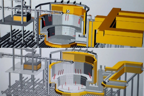
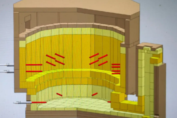
Vertical melting refers to the process in which the raw material undergoes chemical reaction and clarification and homogenization to become qualified glass liquid within a vertical depth of about 1 to 3 meters in an electric melting furnace. Due to different types of glass, the temperature at the bottom of the raw material layer in the furnace is also different, ranging from 1,000 to 1,200°C. The chemical reaction temperature of glass refers to the melting temperature of glass, which is generally between 1,200 and 1,700°C. Therefore, within a height of 1 to 3 meters, the process of raw material from solid to qualified glass liquid is a complex melt movement process. Figure is a schematic diagram of the process principle of the vertical melting furnace, and the specific process can be divided into the following three stages.
(1) The upper part of the electric furnace is the raw material layer.
After the mixture is continuously added, a cold top layer is formed in the furnace, which provides insulation and ensures a reasonable temperature distribution along the height of the furnace.
(2) The upper and middle part of the electric furnace is the melting zone.
The electrodes are arranged reasonably to input electrical energy into the glass liquid. The glass between the electrodes heats up due to resistance heat conduction. The center of the furnace conducts heat due to the flow of high-temperature glass. This is the melting mechanism of the all-electric melting furnace. The entire melting zone is a high-temperature glass turbulent hot zone. Because the distance between the diagonals is the longest, the resistance of the glass is large, and a large electric power can be applied. The electrodes are installed obliquely to reduce the impact of the high temperature at the top on the side walls of the furnace.
(3) The lower part of the electric furnace is the clarification zone.
After the glass liquid reaches the clarification zone, the temperature gradually decreases, the flow tends to be stable, and the qualified glass liquid flows out of the flow hole into the heat treatment zone.
The characteristics of vertical melting are that there is no physical barrier between the melting zone and the clarification zone.
The clarification zone is below the melting zone, and the melting zone area is relatively small. Due to the flow and stirring of glass liquid, during the process of melting glass, the gas generated by the raw material in the melting zone rises, most of the gas is blocked by the raw material mixing layer, and re-solidifies and mixes into the material layer, and a small part of the gas forms bubbles that overflow from the edge of the material layer. However, due to the influence of the viscosity of the glass liquid, the surface tension of the tiny bubbles is greater than the buoyancy of the bubbles, and these tiny bubbles continue to flow downward into the clarification zone. The function of the clarification zone is to remove these tiny bubbles to the maximum extent and finally form qualified glass liquid.
1.2 Cold top layer
The temperature of the upper space of the melting pool of the all-electric melting furnace can be controlled below 150℃, which is called the "cold top". The upper part of the molten glass is a mixed layer formed by batch materials and partially melted raw materials, which can play the role of heat insulation and absorbing the gas produced by the chemical reaction of glass raw materials. The batch materials are added to the upper part of the mixed material layer by an automatic feeder, and the lower part of the mixed material layer is continuously melted. The thickness of the mixed material layer is generally maintained at 20-30cm, and the specific thickness depends on the size of the furnace and the melting speed. The temperature distribution of the cold top layer can be obtained through computer simulation.
Figures are the temperature distribution of hexagonal and rectangular electric melting furnaces respectively. The surface of the material layer is dark and the temperature is low; the longitudinal center is bright red and the temperature is high; at the same height level, the temperature near the electrode area is relatively high.
1.3 Flexible arrangement of electrodes
Cold-top all-electric melting furnaces usually use alternating current as the melting energy source and heat the glass liquid through electrodes (molybdenum or tin dioxide). Depending on the furnace structure and the type of glass being melted, the electrodes can be flexibly arranged. There are three common types, as shown in Figures.
Figure is a computer simulation of the glass liquid flow in a polygonal furnace. It is found that if the distance between the electrodes is large and the resistance of the glass is large, the temperature of the glass liquid in the center of the furnace will be low, the temperature distribution will be uneven, the melting efficiency will be reduced, and the qualified rate of the glass will decrease.
In order to prevent the high-temperature glass liquid flowing on the upper end of the electrode from corroding the refractory material of the furnace wall, the electrode can be inserted inward at a certain angle, as shown in Figure. The use of this oblique bottom insertion electrode can make the upper part of the electrode as close to the lower part of the mixed material layer as possible. The electric field of the electrode is relatively wide, and the range of input electric energy is also relatively large. It can provide the heat capacity required for heating the chemical reaction of the raw material and improve the melting efficiency; at the same time, the current distribution on the electrode surface is relatively uniform, which improves the electric power, not only improves the yield of glass, but also helps to extend the service life of the electrode.
Figure shows a photo of the slanted bottom insertion electrode and the external water jacket of the glass furnace. This electrode cooling water jacket usually has a propulsion structure, which is convenient for workers to operate and maintain. Under normal circumstances, the propulsion operation frequency of the electrode is 1 to 2 times/year, and the service life can reach 2 furnace years.
1.4 Fully covered automatic charging
Usually, the daily output of vertical melting all-electric melting furnaces ranges from several hundred kilograms to tens of tons. Different forms of automatic charging machines can be used to achieve full coverage charging in the furnace to ensure the uniformity of the thickness of the mixed material layer.
However, with the improvement of design, manufacturing and equipment levels, the scale of all-electric melting furnaces is getting larger and larger. For example, the British FSL company built an all-electric melting furnace in France to produce pharmaceutical neutral glass, with a daily output of 200 tons. As the length-to-width ratio of the melting pool continues to increase (such as large rectangular furnaces), it brings huge challenges to the structural design and manufacturing of the cantilevered beam charging machine, as shown in Figure.
1.5 Simple melting process
Figure shows the relationship between time (t) and temperature (T) in the glass melting process, showing the temperature change over time in the process of glass from raw material → melting → chemical reaction → elimination of small bubbles → cooling.
The area contained by the curve represents the energy consumption required to melt the glass. Different processes produce different process curves. From the perspective of production, glass factories always hope to use less energy consumption to obtain qualified glass. Therefore, the T-t curve of glass has a certain guiding significance for the design of all-electric melting furnaces.
• Electrodes can be arranged according to the geometric shape of the furnace, the electric power can be controlled, and the temperature required for melting glass at different stages can be matched through design, as shown in Figure.
1.6 Wide range of cullet addition
Adding cullet to glass melting can save energy and reduce consumption, speed up melting, improve glass quality, promote clarification, and reduce environmental pollution. As the proportion of waste glass added increases, the melting rate of the cold top all-electric melting furnace increases accordingly. As shown in Figure, depending on the type of glass, the proportion of cullet added can reach 20% to 100%.
1.7 High melting efficiency
The cold-top all-electric melting furnace has a simple structure and no heat exchange device, and has good overall thermal insulation performance. This is because the design of the cold top layer effectively reduces heat loss. As shown in Figure, there is no obvious red light above the raw material layer, low high-temperature radiation, and low overall heat loss.
However, the stability of the upper raw material layer in the cold-top all-electric melting furnace is one of the key factors determining the quality of glass products, which is related to the power distribution and flow field stability in the melting pool. The integrity and uniformity of the raw material layer are crucial to maintaining the thermal balance within the system.
As long as there is no hot gas emission, energy loss can be reduced, thereby maintaining a low energy consumption level. In actual operation, when using a cold-top all-electric melting furnace to produce glass, a large amount of gases such as sulfur dioxide (SO2) and carbon dioxide (CO2) may be generated during the "oxidation/reduction" process of the raw material.
► These gases will accumulate under the raw material layer, hindering the effective conduction of heat from the molten high-temperature glass to the raw material layer, reducing the melting efficiency;
► at the same time, excessive gas may also destroy the overall structure of the raw material layer, causing bubbles, thereby weakening the insulation effect of the raw material layer, resulting in a decrease in the melting rate of the cold-top all-electric melting furnace, as shown in Figure.
In order to ensure the good state of the raw material layer, the energy consumption of the cold-top all-electric melting furnace is generally controlled at a level below 3.0 MJ/t, especially when the daily output of the furnace exceeds 200 tons, the energy consumption performance is even better. Therefore, for the production of specific types of glass, the all-electric melting furnace has shown significant technical and economic advantages.
1.8 Simple furnace auxiliary configuration
The structure and system of the all-electric melting furnace are relatively simple, with less equipment, relatively low construction cost, simple daily maintenance, long service life, and short time required for re-cold repair.
The main configuration equipment includes:
(1) Electrode cooling water jacket and measuring sensor
By obtaining information from the measuring sensor, combined with digital simulation method and practical experience, the temperature distribution and flow model of the instant furnace can be qualitatively established. This control technology is in the process of development and has achieved good results. This is an important progress in furnace control technology.
(2) Molybdenum electrode and tin oxide electrode
Molybdenum electrode is a metal oxide solid solution material, which is a metal-based ceramic dispersion reinforced composite (ODS material) formed by zirconium oxide ceramic and molybdenum metal. Because of its high temperature resistance and long service life, it is now widely used in the glass manufacturing industry.
Tin oxide electrode is an electrode made by sintering ultrafine powder doped with conductive medium in high-purity ultrafine tin oxide powder. It is a metal oxide ceramic with little pollution to glass. It can melt glass with a melting point of up to 1,800°C, so it can be used to melt any kind of glass. Tin oxide electrode is usually used to produce special glass, such as LCD TFT glass, lead glassware, decorative glass, high-lead protective glass, rare earth glass, lanthanum high-luminous flux optical glass, high-aluminum high-alkali cover glass and high-grade glass bottles. Since tin oxide has a relatively large specific gravity and is a non-wetting interface with glass, the wear particles generated by the high-temperature glass liquid will not flow with the glass liquid, and the pollution to the glass products is small.
2.How to choose refractory bricks for CTVM furnaces
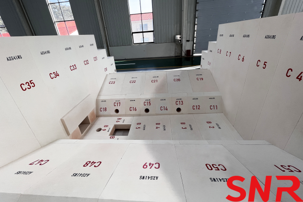
When selecting fused cast AZS blocks for glass electric furnaces, multiple factors need to be considered to ensure that they meet production needs and extend their service life.
First, the composition and characteristics of the glass liquid need to be clarified, because different glass components have different erosion effects on AZS blocks. Understanding the compatibility of glass components and AZS blocks helps to select the most suitable AZS block models, such as AZS-33, AZS-36 or AZS-41, which have different erosion resistance depending on the ZrO2 content.
Secondly, suitable AZS blocks need to be selected according to different parts of the furnace. For example, the melting zone may require AZS blocks with higher corrosion resistance, while the cooling section may pay more attention to its thermal stability and thermal shock resistance. In addition, the density, glass phase quality and impurity content of AZS blocks are also important factors affecting the selection. High-quality AZS blocks have higher density and fewer impurities, and can better resist the erosion of glass liquid.
 At the same time, the quality of the furnace and the operating conditions of the furnace should also be considered. The cracking problem during the furnace heating up, as well as factors such as the temperature in the furnace, the pulling amount, and the glass liquid flow rate, may affect the service life of AZS blocks. Therefore, when selecting AZS blocks, it is necessary to work closely with the furnace design team to ensure that the selected materials can meet the actual operation requirements of the furnace.
In summary, the selection of fused cast AZS blocks used in glass electric furnaces is a complex and meticulous process, which requires comprehensive consideration of glass composition, furnace location, AZS block quality, and furnace operating conditions. Through scientific and reasonable selection, it can ensure that AZS blocks perform at their best in the furnace, improve production efficiency and extend service life.

Henan SNR Refractory Co., Ltd. has been specializing in the production of fused cast AZS blocks for about 25 years. We use high-quality raw materials and advanced fusion technology to provide customers with high-quality products. From raw material procurement to finished product delivery, every step is strictly quality inspected to ensure that every indicator meets the standards, so you can use it with confidence.
 If you have any needs, you can contact me at any time.
 Web:www.snr-azs.com
 Email:wendy@snrefractory.com


