
The glass furnace of a float glass production line is a very complex structure, with different temperatures and environments in each area. Therefore, the materials and properties of refractory materials used in each area are different. At the same time, temperature control for different areas also varies, which imposes many constraints on insulation work. Additionally, since the glass furnace is filled with various gases and raw material powders, the environment in which the refractory and insulation materials of the glass furnace are located is relatively harsh. Suitable materials need to be selected according to specific conditions to achieve good insulation effects while ensuring the safety of the glass furnace.
1. Glass furnace Structure Design
Add a 0# oxygen lance inside the glass furnace to increase the pre-melting temperature of the charging tank and promote the melting of the batch. Increase the number of port pairs, with 3 to 4 burners configured in each port; strengthen the control of each burner to precisely control the temperature at each point. Strengthen the sealing of the inner and outer surfaces of the lower flue channel of the glass furnace, add a layer of castable at the bottom of the flue channel, and add a layer of lightweight clay bricks for insulation to enhance sealing. The regenerator adopts a "2-2-1-1" separation method, with the partition wall extending to the top of the crown to reduce partition wall tilting. The regenerator uses bonded chimney brick. The upper outer wall and partition wall of the regenerator use bonded mullite bricks, the middle wall uses 96% MgO bricks, and the lower part uses low-porosity clay bricks (DN-12/DN-15). Composite insulation coating is applied to the regenerator walls and top crown to reduce surface temperature and heat dissipation. The transition layer lattice bricks at the bottom of the checker, the grate arch, and leveling bricks all use bonded sillimanite bricks. A narrow and long neck structure is adopted to reduce heat loss, while deep cooling water jackets are installed at this location to control the reflux and temperature drop of the glass melt by adjusting the depth of the deep-water jackets.
The rear gable wall of the melting tank adopts a J-type hanging wall, the neck adopts a hanging flat arch, and the front gable wall of the cooling tank adopts an arch structure. The arrangement of the neck hanging flat arch should meet the requirement of position interchange between the deep-water jacket and the horizontal stirrer. The narrow and long neck structure appropriately extends the distance between the deep-water jacket and the stirrer to improve temperature control. The melting tank adopts a deep pool structure, with the glass furnace bottom using a stepped structure. The melting tank depth is 1400 mm, and several steps are set in the clarification zone to strengthen the reflux of the glass melt in the batch area and promote batch melting. The front section of the cooling section breast wall has a water jacket hole, the middle position has a blowing hole, and the end has a water jacket hole with an enlarged brick door to enhance precise control. The melting section crown uses domestically produced high-quality silica bricks, with imported refractory mortar and expansion joint sealing materials for construction. The inner wall of the crown is sprayed with composite insulation coating. A pair of FEF heaters are installed in the cooling section, with the nozzle of the dilution air pipe and the air inlet of the dilution fan all made of high-quality materials. The TV monitoring bricks for the rear gable wall use high-quality zircon bricks. The large damper achieves remote control, with opening adjustment, display, and limit integrated into the DCS control system to strengthen overall control and save energy. An innovative nozzle is installed above the wall cooling air duct to facilitate subsequent operations. A full equal-width charging pool structure is adopted to optimize the glass furnace size. The front wall adopts 45° L-types hanging wall, while the flame deflector brick structure replaces the flame deflector water jacket, and a charging port sealing device is installed to enhance the sealing of the doghouse and pre-melting of the batch. Optimize the distance from the centerline of the 1# port to the front wall to fully utilize the potential of the 1# port and further promote batch melting. Reasonably design the length of the clarification zone of the glass furnace to ensure that deep micro-bubbles have sufficient time to escape while saving energy.
2. Glass furnace Material Selection
The selection of insulation materials generally follows the following principles:
1. High-Temperature Resistance
Operating Temperature Range: Refractory materials must be able to operate stably in high-temperature zones of the glass furnace (e.g., the melting tank can exceed 1500°C) without softening or melting.
Thermal Stability: Strong resistance to thermal shock (rapid heating/cooling) to prevent cracking or spalling.
2. Low Thermal Conductivity
Insulation Efficiency: Refractory materials with low thermal conductivity (e.g., ceramic fiber, lightweight refractory bricks) should be selected to minimize heat loss and reduce energy consumption.
Layered Design: In multi-layer insulation, outer layers may use materials with slightly higher thermal conductivity to cut costs, but the inner layer must provide high-efficiency insulation.
3. Chemical Inertness
Corrosion Resistance: Must withstand chemical erosion from molten glass and volatile substances (e.g., alkali vapors, SO₂) to avoid contaminating the glass (e.g., zirconia bricks are used in glass-contact areas).
Low Volatility: Should not release harmful gases at high temperatures to prevent compromising glass quality.
4. Mechanical Strength
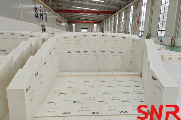
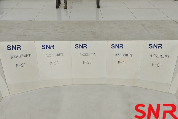
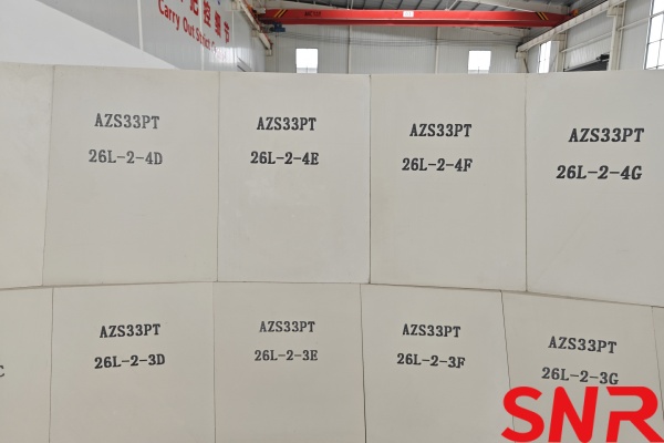
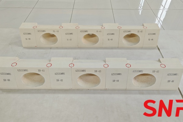
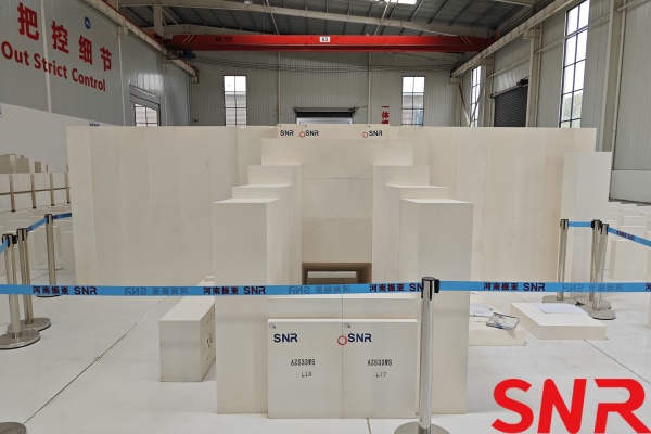
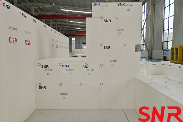
Load-Bearing Requirements: Certain areas (e.g., glass furnace bottom) must withstand the static pressure of molten glass, requiring high-strength materials (e.g., dense fused cast AZS blocks).
Abrasion Resistance: Must withstand airflow or erosion from raw materials to prevent pulverization.
5. Thermal Capacity and Response
Heat Capacity Selection: Regenerators require high-heat-capacity materials (e.g., magnesia bricks) to store heat, while insulation layers may use low-heat-capacity materials for rapid temperature adjustment.
6. Cost-Effectiveness and Longevity
Cost Balance: Critical areas (e.g., the melting tank) should use high-cost, long-lasting materials (e.g., fused cast AZS refractories), while non-critical zones can use cost-effective lightweight bricks.
Maintenance Cycle: Material lifespan should align with the glass furnace overhaul schedule to minimize downtime losses.
7. Ease of Construction and Maintenance
Formability: Fiber modules or moldable plastics are suitable for complex shapes, while brick materials require consideration of masonry techniques.
Repairability: Localized damage should be quickly repairable (e.g., via refractory spray coatings).
8. Environmental and Safety Compliance
Non-Toxicity: Avoid carcinogenic materials (e.g., traditional asbestos) and opt for eco-friendly fibers (e.g., biosoluble fibers).
Waste Management: Consider recyclability or safe disposal of decommissioned materials.
Generally, the crown top, glass furnace bottom, and walls of a float glass furnace are areas with high heat dissipation. Usually, the heat dissipation from these parts accounts for 80% to 90% of the total heat dissipation of the glass furnace body. The heat transfer methods on the outer surface of the glass furnace are mainly convection and radiation heat transfer. The amount and speed of heat transfer depend on the surface temperature of the glass furnace body and the external environmental temperature. The smaller the temperature difference between the glass furnace body surface and the external environment, the lower the heat loss. Therefore, according to this principle, to achieve the purpose of insulation and energy saving by reducing heat exchange between the glass furnace and the external environment, measures can be taken to reduce the surface temperature of the glass furnace body. By effectively insulating the glass furnace body, the surface temperature after insulation can be reduced as much as possible. The reduction in this temperature is closely related to the physical properties of the selected insulation material, especially the thermal conductivity coefficient of the insulation material, which is positively correlated. In addition to insulation materials, the refractory materials of the glass furnace body also need to consider changes after adding an insulation layer on the outer surface. Therefore, the refractory materials of the glass furnace tank usually also need to take into account erosion resistance. Key parts use high-quality fused cast AZS blocks, with fused cast AZS blocks containing 33% to 41% ZrO₂ being the most widely used. This material has good erosion resistance.
As an important carrier for heat storage and heat exchange, the regenerator is also very critical for energy saving. Usually, the regenerator adopts a "2-2-1-1" separation method, with the partition wall extending to the top of the arch to reduce partition wall tilting. The regenerator uses bonded chimney brick. The upper outer wall and partition wall of the regenerator use bonded mullite bricks, the middle wall uses 96% MgO bricks, and the lower part uses low-porosity clay bricks (DN-12/DN-15). Composite insulation coating is applied to the regenerator walls and top arch to reduce surface temperature and heat dissipation. The transition layer lattice bricks at the bottom of the checker, the grate arch, and leveling bricks all use bonded sillimanite bricks. The top three layers of the 1# to 5# checker use chrome corundum bricks.

3. Insulation Enhancement Measures
The Energy Saving and Environmental Protection Institute of Bengbu Glass Industry Design & Research Institute, CNBM, through years of research on glass furnace insulation technology, broke the conventional thinking of traditional insulation and creatively invented the "Gradient Composite Thermal Insulation Technology for Glass furnaces" in addition to the glass furnace body insulation measures. This enhanced insulation measure completely changes the characteristics of traditional insulation such as "poor insulation performance, large insulation attenuation rate, poor durability, and easy falling off." The "Gradient Composite Thermal Insulation Technology for Glass furnaces" is mainly aimed at different parts of the glass furnace. Through strict thermal simulation and precise thermal calculation, the optimal insulation scheme is designed: according to the gradient heat loss characteristics from inside to outside the glass furnace, the insulation layer is divided into several temperature segments according to temperature ranges. Based on the temperature characteristics of each segment, suitable insulation materials with "good temperature resistance, strong insulation performance, and strong material durability" are scientifically selected. The outermost layer of the insulation layer adopts fiber spraying technology, which has the characteristics of "low thermal conductivity, no cracking, and smooth and fine surface".
Usually, the insulation of various parts of the glass furnace should also pay attention to the following matters:
1. Melting Zone
♦ The glass-contact inner layer must utilize high-density, erosion-resistant materials (e.g., fused cast AZS blocks) to prevent glass penetration and insulation failure.
♦ A transition layer (e.g., high-alumina bricks) should be installed between the insulation layer and working layer to alleviate thermal stress.
♦ For upper structures (crown, breast walls), excessive insulation thickness must be avoided to prevent crown overheating, requiring a balance between insulation and refractory lifespan (silica brick crowns are typically maintained below 1650°C).
♦ Adopt multi-layer composite structures (e.g., silica bricks + ceramic fiber blankets) with expansion joints reserved at the top.
2. Refining Zone
♦ Insulation materials must resist alkali vapor corrosion (e.g., K₂O/Na₂O), with preference given to zirconia-containing alumina-silicate fibers or low-porosity refractory bricks.
♦ Avoid using silica-based materials (e.g., standard silica bricks) that easily react with volatiles.
3. Regenerator
High heat capacity and thermal shock resistance:
♦ Checker bricks should use magnesia or magnesia-chrome bricks to balance heat storage and thermal shock resistance.
♦ Wall insulation must align with heat recovery needs, avoiding excessive insulation that could reduce efficiency.
Clogging prevention:
♦ Avoid using easily pulverized insulation materials to prevent debris from blocking the checker channels.
4. Throat & Forehearth
Temperature gradient management:
♦ The throat area requires enhanced insulation (e.g., nano-porous panels) to minimize temperature fluctuations and prevent glass crystallization.
♦ Forehearth insulation must be precisely controlled (e.g., multi-layer lightweight bricks + fiber modules) to ensure stable glass viscosity.
5. Glass Furnace Bottom
Load-bearing and leakage prevention:
♦ The base layer should use high-strength refractory concrete or dense fireclay bricks, the middle layer lightweight insulation bricks, and the top layer an erosion-resistant material (e.g., fused cast AZS blocks).
♦ Temperature monitoring points should be installed to detect insulation performance and prevent localized overheating, leading to glass penetration.
6. Flue & Waste Heat Recovery System
Acid corrosion resistance:
♦ Flue insulation must withstand acidic condensates (e.g., H₂SO₄), using acid-resistant castable or fiber-reinforced materials.
♦ The waste heat boiler interface should accommodate thermal expansion with flexible sealing structures.
7. Special Areas (Inspection Ports, Electrode Ports, etc.)
♦ Inspection ports should feature removable insulation modules (e.g., ceramic fiber foldable blocks) for maintenance convenience.
♦ Electrode ports should employ high-thermal-conductivity sealing materials (e.g., graphite felt) to prevent localized overheating.

4.Conclusion
Through comprehensive energy-saving and insulation measures such as optimized structural design of the float glass furnace, reasonable selection of refractory and insulation materials, and innovative gradient composite thermal insulation technology for glass furnaces, the principle of insulating wherever possible is achieved. The above measures have been used in practice in multiple glass furnaces and have achieved very good results. Practice has proven that these solutions and measures have the characteristics of scientific planning, economic practicality, and low investment with high returns. It is hoped that more and better insulation measures can be innovated in future projects.
Henan SNR Refractory Co., Ltd. is dedicated to the manufacture, research and development of fused cast AZS refractory materials and bonded refractory materials for the glass industry. Meanwhile, SNR can provide total solutions and services for glass furnace design, glass furnace construction, renovation, and upgrading. Please contact me if you have any requirements.
CONTACT: zoe@snrefractory.com/ WhatsApp:+86 18172389584
 info@snr-azs.com
 +86-18203976036