
 Ⅰ.Melting Process
Ⅱ.Sand Mold Production
Ⅲ.Casting
Ⅳ.AZS Annealing Process
Ⅴ.Conclusion
1.1 AZS Raw Materials
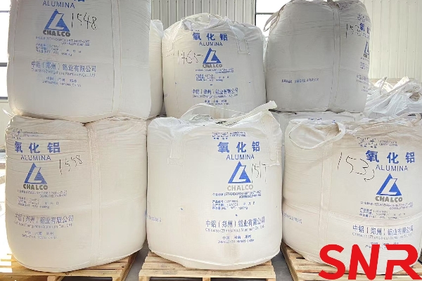
Fused cast AZS block uses five types of raw materials: alumina, zircon sand, zirconium-rich sand, soda ash, and borax.
Alumina: Industrial alumina is typically used, with production requirements specifying a moisture content of less than 0.3% and a loss on ignition preferably below 0.15%. Approximately 0.62 tons of alumina are required per ton of fused cast AZS #33 block.
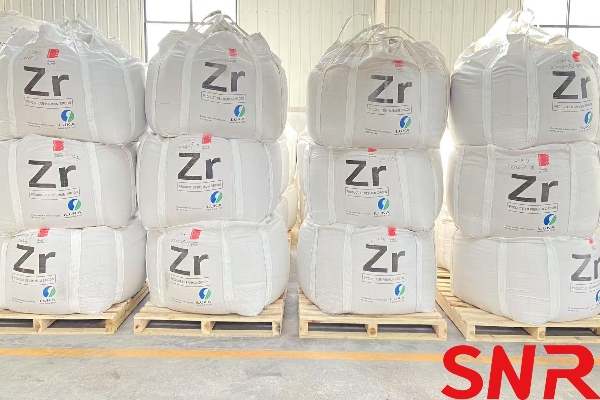
Zircon Sand: Primarily introduces ZrO₂ and SiO₂ but also contains small amounts of Fe₂O₃ and TiO₂, which can discolor AZS products, cause coarse crystal sand holes, and affect cracking during cooling. Thus, their content should be less than 0.2%. Additionally, these impurities can impact the oxidation process, so their content must be restricted to below 0.2%. Approximately 0.65 tons of zircon sand are needed per ton of fused cast AZS #33 block.
Zirconium-Rich Sand (Desilicated Zircon): All SiO₂ in AZS is sourced from zircon sand. Any deficiency is supplemented by zirconium-rich sand.
Soda Ash: Introduces Na₂O as a flux for AZS blocks. A secondary grade is typically used, with about 20 kg of soda ash required per ton of fused cast AZS #33 block.
Borax: Also acts as a flux for AZS blocks, with approximately 20 kg needed per ton of fused cast AZS #33 block.
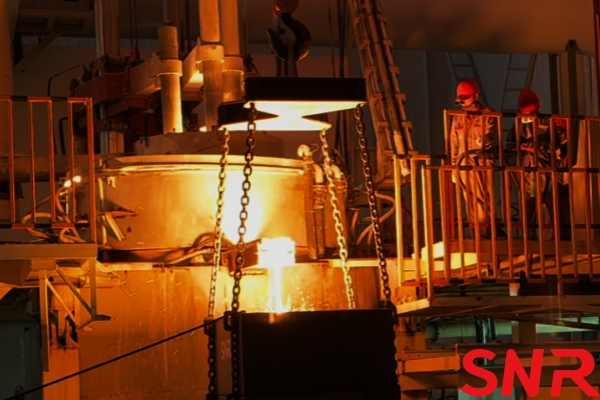
1.2 Electric Arc Furnace Working Principle
The furnace body consists of a furnace bottom, furnace walls, and a furnace roof. Three graphite electrodes are inserted through the roof in a triangular arrangement. A 5–10 kg arc-starting coke is placed at the central projection of the three electrodes. After compacting the coke, the three-phase electrodes are lowered simultaneously. When the electrodes contact the coke, an arc is initiated simultaneously across all three electrodes. After ignition, material is slowly added, ensuring the arc is not extinguished while keeping the current below the rated value. Typically, the current stabilizes within half an hour of ignition, after which the control phase begins.
The resistance of the mixed raw materials is very high. When the arc strikes the mixture, immense heat is generated, melting the materials.
1.3 AZS Melting Principle
The AZS melting process has four objectives:
Melting the alumina in the raw materials and recrystallizing it into corundum.
Decomposing zircon sand, melting the resulting zirconia, and recrystallizing it into baddeleyite.
Using sodium and boron as modifiers to suppress mullite formation and react with SiO₂ to form the desired glass phase in the product.
Producing a molten liquid with uniform chemical composition, minimal carbon content, few bubbles, and suitable temperature and casting properties to ensure high-quality products.
1.3.1 Physical and Chemical Reactions During Melting
1) Alumina:
Liquid Al₂O₃ crystallizes into corundum upon cooling.
2) Zircon Sand:
Mainly composed of zirconium silicate (ZrSiO₄), which decomposes as follows:
ZrSiO4→ZrO2+SiO2
The melting point of zircon sand is 2430°C, but with the fluxing agents in AZS, this high temperature is unnecessary. Ultimately, ZrO₂ transforms from a low-temperature crystalline form (hexagonal) to a high-temperature form (tetragonal) as baddeleyite.
3) Soda Ash and Borax:
Soda ash decomposes into Na₂O, and borax decomposes into Na₂O and B₂O₃. These then react with SiO₂ from zircon sand and impurities like Fe and Ti to form silicate glass.
4) Insufficient Sodium Oxide:
Some SiO₂ in the melt forms mullite, an undesirable crystalline phase in the product.
5) Melting Process:
As the electrodes continuously burn, the following reactions occur:
Some SiO₂ is reduced by carbon:
In the cooler upper part of the furnace, silicon is oxidized to form SiO₂, which precipitates as white, cotton-like material.
6) Moisture in Raw Materials or Mixture:
Under high temperatures, moisture decomposes, releasing hydrogen that dissolves into the melt. This causes foaming or poor contraction, leading to dispersed shrinkage pores or numerous pinholes in dense sections. While some assume moisture evaporates in the furnace, observations show that the material layer collapses directly into the high-temperature melt at the arc site without a drying phase. The furnace temperature is so high that the material immediately sinters, leaving no time for drying. Thus, raw materials must be dry to produce dense products.
1.4 Melting Techniques
AZS melting techniques are divided into the reduction method and the oxidation method.

1.4.1 Reduction Method
Also known as the submerged arc method, this involves embedding graphite electrodes in the furnace charge. Since the electrodes burn in an oxygen-deficient atmosphere, a series of reduction reactions occur, reducing certain high-valence oxides in the melt to unstable low-valence states. Carbon also infiltrates the melt, darkening its color. Even if the arc is short or the electrodes are semi-submerged, partial exposure of the arc still falls under the reduction method.
1.4.2 Oxidation Method
In this method, the furnace charge is melted without carbon infiltration, or any infiltrated carbon is removed before casting. This ensures the final melt is carbon-free, earning it the name "open arc method."
Since the reduction method leaves carbon in AZS blocks, which burns at high temperatures in glass furnaces, releasing gases that expel softened glass phases and accelerate corrosion by molten glass, carbon presence is detrimental to AZS block erosion resistance. Thus, the oxidation method is now preferred.
Carbon in AZS blocks mainly comes from unburned graphite electrodes entering the furnace during arcing. To prevent carbon infiltration, the following decarburization methods are commonly used in production:
Long Arc Method:
The electrodes are not immersed in the melt, eliminating carbon transfer between the electrodes and the melt. The arc length is sufficient to ensure complete oxidation of carbon before it reaches the melt, volatilizing as CO₂ or CO. An open arc length of about 50 mm qualifies as long-arc melting. Methods using argon to protect the electrodes also fall under long-arc melting, as the arc ionizes the argon, inhibiting carbon oxidation or infiltration into the melt, thereby reducing electrode consumption.
Oxygen Blowing Method:
Various implementations exist, but all involve blowing oxygen into the melt after reduction melting. Some insert oxygen lances through the furnace roof, while others position them at the furnace spout, tilting the furnace to submerge the lance in the melt for oxygen injection. Trace carbon in the melt burns off upon contact with oxygen.
Oxidizing Agent Addition Method:
Oxygen-rich raw materials are added to the mixture, releasing oxygen during melting to burn off carbon on the melt surface. However, this alone is insufficient. Typically, open-arc melting is used first, followed by arc melting during the refining stage. To increase arc length and stability, ionizing substances like sodium carbonate are added along with oxidizing agents during the later stages of melting. As the melt swirls under the arc‘s agitation, the entire furnace melt undergoes some degree of purification.
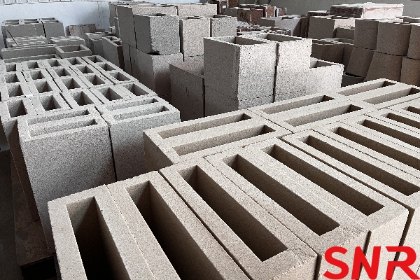
Ⅱ. Sand Mold Production
2.1 Raw Materials for Sand Mold Preparation
Given the casting temperature of AZS blocks reaches approximately 1800°C, sand molds are suitable for this process. The primary materials used are natural sand and quartz sand, with varying particle size distributions to enhance the mold‘s strength. Quartz sand is categorized into fine sand and facing sand, both with a silica content exceeding 99%. Each sand mold‘s casting surface is coated with a layer of facing sand to prevent contamination.
Various binders can be employed, but sodium silicate (water glass) is commonly preferred due to its stable quality, affordability, easy washability, odorless nature, and ability to meet the following technical requirements when combined with high-purity silica sand:
Good Gas Permeability: Gases released from the AZS melt can escape through the gaps between silica sand particles in the mold wall.
Excellent Thermal Shock Resistance: The thermal shock during casting creates a significant temperature gradient between the inner and outer walls of the mold. However, the sand mold remains stable under heating, as its refractoriness exceeds 1690°C, and its linear expansion coefficient between 20–450°C is approximately 0.03 mm/°C, enabling it to withstand the static pressure of high-temperature molten flow without cracking.
Good Thermo-Mechanical Properties: The mold‘s strength decreases upon heating. Load softening tests indicate softening begins around 320°C, with degradation starting at 400°C.
No Chemical Sand Adhesion on AZS Surface: Upon contact with the AZS melt, the sand mold rapidly cools and hardens, forming a thin layer of sodium silicate or silica on its surface that does not react with AZS. Experimental results show that the optimal sodium silicate content is 5.7%. Lower amounts reduce refractoriness, while higher amounts hinder mold formation.
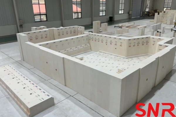
2.2 Sand Mold Manufacturing Process
Large wet sand molds often develop cracks during handling before furnace placement. To enhance strength, holes are drilled into the mold, and carbon dioxide is injected. Due to the low solubility of silicic acid, it precipitates, providing the wet sand mold with temporary strength.
The prepared molds are dried in a resistance furnace to achieve sufficient strength for casting, with a maximum drying temperature of around 400°C.
Ⅲ. Casting
After the raw materials undergo melting and refining in the electric arc furnace, the molten liquid is directly poured into the mold—a process known as casting. Although brief, each step critically impacts the final product‘s quality, making it a complex stage. Below are several common casting methods used in China:
3.1 Casting Methods
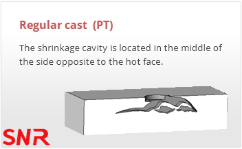
Conventional Casting (Code: China PT; Corning, Asahi, Toshiba RC; SEPR RN): The casting employs a standard riser, which is removed while hot. The cross-section divides into two parts: one solidifies first with fine crystals (40–50% of the thickness), while the other solidifies later, containing shrinkage pores and coarse crystals. This method produces cost-effective blocks, often used in glass furnace superstructures and sidewalls of clarifier zone.
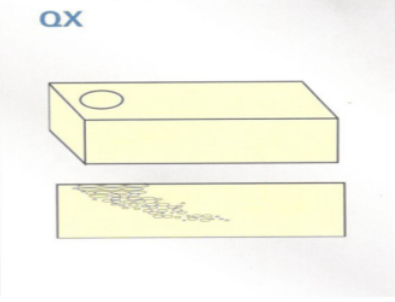
Tilt Casting (Code: China QX; Corning TA, Asahi TC, Toshiba TCL; SEPR RO): The mold is tilted before casting, with the riser placed at one end. This ensures a dense zone at the top (T-section) while maintaining high dimensional accuracy in the T-direction. Such castings are ideal for vertical wall construction.
Shrinkage-Free Casting (Code: China WS; Corning, Asahi VF; Toshiba DCL):
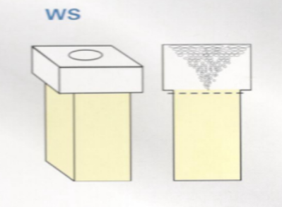
Method 1: Shrinkage pores are concentrated in a specific area and later removed with a diamond saw, leaving a dense, uniform structure with a density close to the theoretical value.
Method 2 (Leg Cutting): The casting is shaped like an "L," with most shrinkage pores concentrated in the smaller leg (60% of the volume). The entire casting remains embedded in insulation during annealing, tilted to direct shrinkage toward the leg. Due to high cutting costs (diamond saw expenses often exceed the block‘s price), this method is used sparingly.
3.2 Characteristics of the Casting Process
The casting process significantly influences product quality, affecting both external integrity and internal structure. Key features include:
1.Intense Heat Exchange and Chemical Reactions: The high-temperature melt rapidly cools while heating the mold, causing decomposition and gas generation, which increases cavity pressure and may lead to defects like gas pockets or incomplete filling.
2.Unstable Flow: Irregular flow rates or turbulence can cause defects such as bulges, cold shuts, or hollow shells near the gate.
3.Porous Mold Filling: The permeable sand mold may draw in external gases (causing porosity) or allow melt infiltration (causing sand adhesion).
4.Time-Dependent Temperature Distribution: Casting duration affects the temperature gradient within the casting.
3.3. Casting Process
The casting process includes casting temperature, casting speed, casting time, and repouring.
3.3.1 Casting Temperature
Casting temperature refers to the temperature of the molten liquid when poured into the mold, typically measured using an optical pyrometer near the furnace spout. For AZS blocks under intensified melting conditions, the casting temperature can reach 1820–1840°C. The viscosity of the melt depends on its chemical composition and temperature, with the composition determined by the formula. Thus, temperature plays a critical role: higher temperatures reduce viscosity, improving fluidity and mold-filling capacity.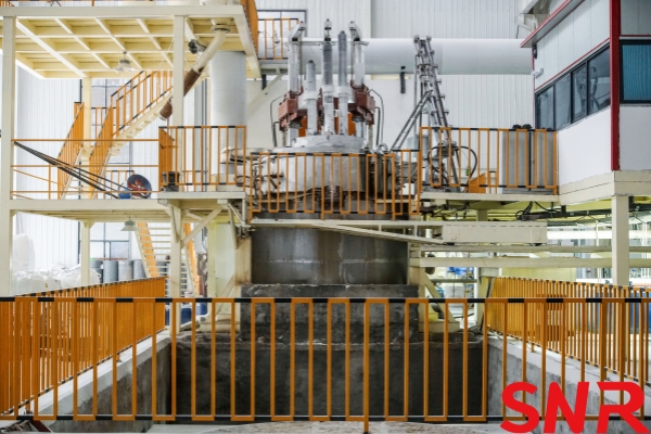
However, excessively high casting temperatures are not ideal. If the temperature is too high, the temperature difference between the casting and the mold decreases, widening the solidification zone from the surface inward and accelerating shrinkage during solidification. This increases shrinkage stress while coarsening initial grain structure and causing compositional segregation. The core of the casting, which solidifies last, is particularly prone to hot cracking, especially in larger castings. Therefore, upper and lower temperature limits should be set based on the casting‘s size and shape to prevent cracking and ensure adequate mold-filling capacity.
3.3.2 Casting Speed and Time
Casting speed determines casting time. Each casting has an optimal casting time, and deviations can lead to defects.
Excessive Speed: A thick, fast-flowing stream exerts high impact force on the mold, potentially breaking or melting part of it, causing protrusions in the casting. Additionally, rapid pouring entrains gas bubbles, which rise to the mold‘s top. The melt contacting the top forms a thin shell, trapping gas beneath and creating hollow cavities. Entrained gas can also form bubbles in the casting. Moreover, high-speed pouring may carry unmelted material from the furnace spout into the melt, causing inclusions.
Insufficient Speed: Slow pouring results in defects such as edge porosity, scarring, sand inclusions, and incomplete filling. A thin stream may solidify into small balls before reaching edges, causing porosity. If the initial melt solidifies into a thin shell and contracts, subsequent melt may flow into gaps between the shell and mold, creating surface scars. Prolonged casting also overheats the mold cover, causing it to flake off and contaminate the melt.
3.3.3 Repouring
Repouring involves refilling shrinkage cavities with molten liquid after the initial casting has cooled and contracted. Small blocks solidify too quickly for repouring, medium-sized blocks allow short intervals, and large blocks permit longer repouring times. Repouring effectively reduces shrinkage porosity and increases density, functioning similarly to enlarging the riser. The key lies in timing the repouring correctly. Multiple sequential repouring cycles are crucial for achieving high-density products.
3.4. Relationship Between Casting and Gas Porosity
Shrinkage cavities and porosity are normal in conventionally cast AZS products, but excessive gas porosity significantly reduces quality.
Gas pores fall into two categories:
Microscopic pores: Visible only under a microscope in thin sections.
Macroscopic pores: Visible to the naked eye, commonly referred to as blowholes.
These pores originate from four sources: raw materials, melting process, mold materials, and casting operations. Below, we focus on mold and casting-related porosity.
3.4.1 Porosity Caused by Mold Materials
Two types of pores are commonly observed at the mold-casting interface:
1.Subsurface honeycomb pores: Perpendicular to the mold wall, these result from moisture on the mold surface. Water is a gas-generating substance—when heated to 1000°C, its volume expands 1700 times (and nearly 10,000 times at casting temperatures). This sudden gas generation creates high pressure, forcing gas into the solidifying edge of the melt and forming elongated pores. Thus, using damp molds is strictly prohibited.
2.Subsurface spherical pores: Single round bubbles within 10 mm of the edge, caused by binder decomposition upon contact with the melt. Some gas escapes through mold pores, while excess gas trapped due to poor venting invades the melt. Improving mold permeability (e.g., using rounded sand grains, removing dust, ensuring higher backside permeability) and ensuring progressive outward venting are critical.
3.4.2 Porosity Caused by Casting Operations
Three types occur: top-surface hollow shells, foam-layer pinholes, and others.
1.Hollow shells: Rapid pouring with poor venting traps gas at the mold‘s top dead zones, forming large hollow cavities beneath a thin shell. To prevent this, casting should start with a thick, fast stream and transition to a slower, thinner flow—except near the end, where slightly faster pouring avoids incomplete filling. Mold covers must be weighted or held down to resist melt pressure.
2.Foam layers: Insulation materials or debris falling into the mold react with the initial melt, forming a rigid bubble layer that floats to the top and solidifies. Mold cavities must be cleaned before casting.
3.Pinholes: Common in the first casting if the furnace spout is contaminated with unmelted material or oxidized graphite powder. These react violently with the melt, generating bubbles trapped due to high viscosity. Keeping melt channels clean is essential.
Other causes include:
Damp raw materials or insufficient melting temperatures, leading to dispersed shrinkage ("bread loaf" porosity).
Neglected practices:
Moving electrodes pre-casting, which dislodges graphite powder into the melt, causing porous inclusions.
Casting under live electrodes, where ongoing reactions produce non-dense melt and castings.
Casting with unmelted material (especially near the spout), which disrupts microstructure and generates pores.
3.5 Defects in the Casting Process and Preventive Measures
3.5.1 Defects in the Casting Process
3.5.1.1 Shrinkage of Castings
Defects such as shrinkage cavities, porosity, internal stresses, cracks, and deformation are all related to the shrinkage that occurs during the solidification of the molten material. The shrinkage of castings can be divided into three stages: liquid shrinkage, solidification shrinkage, and solid shrinkage.
For AZS with a fixed composition, its liquidus temperature is constant. Therefore, the higher the casting temperature, the greater the liquid volume shrinkage. Solidification shrinkage manifests as a continued drop in the liquid level within the mold cavity. Thus, the combination of solidification shrinkage and liquid shrinkage is the primary cause of shrinkage cavities in castings. The volume shrinkage of this portion of AZS can reach 12%–15% due to the known density difference.
3.5.1.2 Formation of Shrinkage Cavities in Castings and Influencing Factors
Formation of shrinkage cavities:
When the molten material in the mold solidifies layer by layer from the mold wall inward, if the reduction in molten material caused by liquid and solidification shrinkage is not compensated, concentrated shrinkage cavities will form in the last areas to solidify.
As the edge temperature of the casting drops below the solidus temperature, a hardened shell forms on the surface, creating a sealed container enclosing the remaining liquid. Further cooling causes the liquid inside the shell to undergo both liquid shrinkage (due to continued temperature drop) and solidification shrinkage (due to shell thickening). Without replenishment, the liquid level drops. Simultaneously, the solid shell shrinks due to cooling, reducing the casting‘s external dimensions.
Since the liquid and solidification shrinkage of AZS melt far exceed the solid shrinkage of the shell, the liquid surface separates from the shell‘s top under gravity, forming a shrinkage cavity. As solidification progresses, the shell thickens, and the liquid level continues to drop. After complete solidification, a shrinkage cavity forms in the core below the casting‘s gate.
If the gas content in the shell-enclosed liquid is low, the shrinkage cavity becomes a vacuum when the liquid surface separates from the shell. The thin upper shell may then collapse inward under atmospheric pressure, resulting in both an external depression and an internal shrinkage cavity.
Factors affecting shrinkage cavity volume:
Greater liquid shrinkage → larger shrinkage cavity
Greater solidification shrinkage → larger shrinkage cavity
Greater solid shrinkage → smaller shrinkage cavity
Slower casting speed → smaller shrinkage cavity
Higher mold chilling capacity → smaller shrinkage cavity
3.5.2 Formation of Porosity in Castings and Influencing Factors
Porosity refers to dispersed fine voids, coarse crystals, or clustered crystal aggregates below shrinkage cavities, visible to the naked eye. Its formation is mainly related to melt composition, solidification characteristics, and the casting‘s solidification sequence.
When the casting has strong crystallinity, coarse crystals grow freely in the last-to-solidify shrinkage areas. In AZS, these are often large columnar corundum crystals with hexagonal baddeleyite crystals on their surfaces. For slender castings where peripheral solidification makes melt feeding difficult, axial porosity forms in the lower sections.
3.5.3 Basic Methods to Reduce Porosity and Shrinkage Cavities
Establish rational casting processes to effectively control solidification and create favorable feeding conditions, transforming porosity into concentrated shrinkage cavities that migrate toward the last-solidifying areas. By adding risers, these cavities can be directed into the risers, yielding dense products.
Solidification modes:
Directional solidification: Artificially creating a gradually increasing temperature gradient from the casting‘s end (farthest from the riser) to the riser, ensuring sequential solidification toward the riser for effective feeding.
Layer-by-layer solidification: Natural solidification where the surface layer solidifies first, progressing inward.
Note: Directional solidification may cause large temperature differences between casting sections, increasing risks of cracks and residual stresses.
3.5.4 Risers
3.5.4.1 Functions and Feeding Principles of Risers
Risers are non-casting appendages designed to compensate for solidification shrinkage. They serve to:
 Reduce shrinkage cavities
Vent gases
Act as observation ports
Design requirements:
Riser size, shape, and quantity must ensure it solidifies last and has sufficient volume to feed the casting‘s shrinkage.
Feeding principle:
A temperature gradient must exist toward the riser during solidification. A dense, shrinkage-free casting is achieved when the riser and end zones are connected without an intermediate non-gradient zone (which causes axial porosity).
3.5.4.2 Riser Design
Riser design encompasses shape, size, quantity, and disposal methods.
1) Riser Shape
According to the principle of riser feeding, the riser must be the slowest solidifying part. Therefore, when designing a riser, the primary requirement is to minimize heat dissipation. The shape should minimize surface area for the same volume, resulting in slower heat dissipation. Calculations show that a sphere has the smallest surface area, followed by a cylinder, a cube, and so on. Riser design also needs to consider practical manufacturing challenges, so spherical risers are not used in AZS production.
2) Riser Size
This primarily refers to the diameter and height. Due to the complex shapes and varying sizes of castings, the required risers cannot be the same. Therefore, a feeding modulus—the ratio of riser volume to casting volume—is introduced to select the riser size with the goal of controlling the unit weight of the casting. Large-volume risers are effective in increasing the bulk density of castings. Large-volume risers can be implemented in various forms, including one large riser, two medium risers, or a single riser that is replaced with a new one after use. Regarding riser height, it‘s generally believed that the higher the riser, the greater the hydrostatic pressure and the more effective the shrinkage feeding effect. In reality, if the riser is too high, it will not be able to withstand the hydrostatic pressure of the melt and will bulge outward. This will also result in cracks at the bottom of the casting after annealing. Therefore, unilaterally increasing the riser height without improving other process conditions is not advisable. Based on the AZS rule that shrinkage porosity accounts for half of the casting height, the design principle for riser height should be consistent with the casting height, with a 1:1 ratio.
3) Number of Risers and Treatment Methods
Typically, one riser is used per casting. For ordinary castings, two risers are used for castings over 700 mm in length. There are two methods for riser treatment: cold cutting and hot scraping. Cold cutting: When the riser is annealed together with the casting, it must be cut with a diamond saw blade. Hot scraping: After casting, wait for the riser feeding to complete before removing the riser. The casting mouth is then covered with a sand mold plate and annealed. The timing of hot riser removal is crucial. If done too early, the riser‘s effectiveness is diminished, molten metal overflows, and the sprue protrudes, increasing the amount of cold work required. Conversely, if done too late, the casting is prone to internal cracking. Therefore, depending on the size of the mold and the riser, this time is generally controlled to 12-40 minutes, keeping the sprue surface slightly below the casting surface and maintaining a smooth, aesthetically pleasing appearance.
Ⅳ. AZS Annealing Process
4.1 Solidification of the Casting
The holding annealing process for castings is the process by which the casting transitions from liquid to solid, and can be divided into four stages:
1) Stage 1: The outer shell of the casting hardens, while the core remains liquid and can flow freely. At this stage, even cracks are immediately healed by the molten metal, even under external forces.
2) Stage 2: The casting is mostly solid, with a small amount remaining liquid. The solid phase precipitated from the core has formed a complete skeleton and possesses a certain degree of strength, but the liquid glass phase is very weak. Under significant stress, the crystalline skeleton will be destroyed, and the isolated, viscous glass cannot fill it, resulting in cracks, commonly known as thermal cracks.
3) Stage 3: The casting is completely solidified and in a plastic state. Any minor stresses occurring during this period are absorbed by the plastic deformation of the glass phase. If the stresses are large enough to exceed the strength limit of the glass phase, cracks will form, also known as thermal cracks.
4) Stage 4: The casting transitions from a plastic state to an elastic state. Since this transition does not occur suddenly and there is no strict critical temperature, the transition temperature is considered to be within the elastic-plastic temperature range.
4.2. Annealing of Castings
Cracks in fused-cast products, whether cold or hot, are caused by casting stresses. To eliminate casting stresses and reduce the chance of cracking during cooling and use, appropriate annealing methods and processes must be selected.
Annealing of fused-cast refractory materials begins after casting at 1800°C, while true annealing begins after the casting reaches its elastic-plastic temperature of 1150-1200°C. Annealing methods are divided into two categories: holding annealing and external heat annealing.
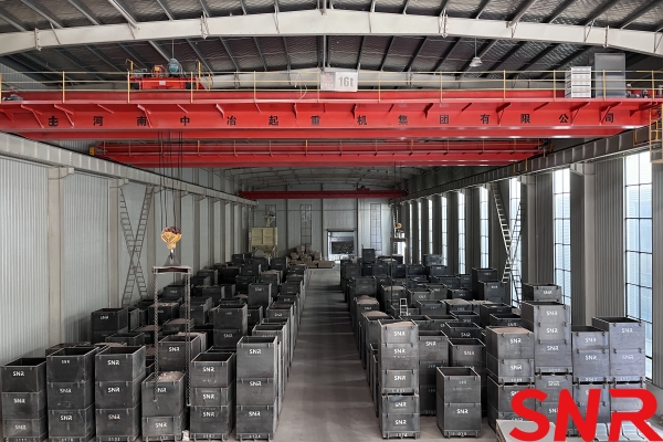
4.2.1 Insulated Box Annealing Method
Use an iron basket suitable for the mold length. Secure a large, solid clay brick to its bottom. Add a sand box sleeve (welded with iron plates) to the mold. Fill the space between the mold and the sleeve with clinker sand or quartz sand to secure the mold. This structure has proven effective in practice because the clinker sand surrounding the mold provides insulation. First, it dissipates heat much more slowly than the original iron basket mold cooled directly in the air. Second, the thick clay brick absorbs heat at the bottom of the mold, creating a temperature gradient toward the casting mouth. Third, using a solid clay brick as the base plate promotes a smooth bottom of the casting. Fourth, the combined mold is secured with clinker sand, ensuring surface contact with the mold walls and applying uniform force, making the casting less susceptible to deformation or mold leakage.
4.2.2 Tunnel Kiln Annealing
The tunnel kiln annealing method involves removing the cast casting from the mold and hoisting it directly onto the tunnel kiln car for annealing according to the specified annealing schedule. Tunnel kilns used for annealing molten cast products differ from those used for firing refractory materials. These kilns include a holding zone, a cooling zone, and a cooling zone, but no preheating zone. After pouring, castings should be placed in the holding zone of the tunnel kiln as soon as possible. The purpose of holding the castings is to ensure solidification and cooling under optimal cross-sectional temperature differences. Temperature differences within the castings are important to maintain layer-by-layer solidification characteristics, while also preventing excessive thermal stresses caused by excessive temperature differences.
The holding temperature should typically be close to the surface temperature of the casting after demolding; the actual holding temperature should be determined based on the specific product. The residence time of the castings in the tunnel kiln and the trolley system should be determined based on the annealing curve. Burners are installed in the holding zone to maintain the holding temperature. To ensure the cooling rate in the cooling and cooling zones, a certain amount of hot air can be drawn from different sections of the holding bag and fed into different sections of the cooling zone.
The development of fused zirconia-alumina blocks started relatively late, but has grown rapidly. By 2025, China‘s fused zirconia-alumina block (AZS block) industry had made significant progress in technology research and development, production processes, and market applications. The next steps are to improve processes, overcome product defects, and develop new products to extend product lifespan.
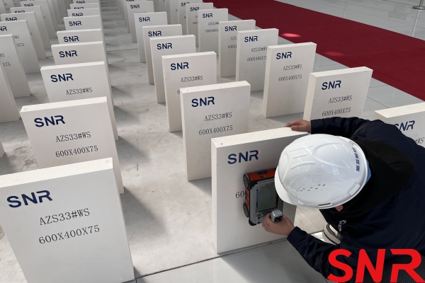
Henan SNR Refractory Co., Ltd. has been specializing in the production of fused cast AZS blocks for about 25 years. We use high-quality raw materials and advanced fusion technology to provide customers with high-quality products. From raw material procurement to finished product delivery, every step is strictly quality inspected to ensure that every indicator meets the standards, so you can use it with confidence.
 If you have any needs, you can contact me at any time.
Web: www.snr-azs.com
Email:wendy@snrefractory.com
 info@snr-azs.com
 +86-18203976036