
Introduction
The glass industry is a sector with substantial energy consumption, among which the furnace is one of the primary energy-consuming pieces of equipment. Due to the high-temperature operation and prolonged running of furnaces, their energy consumption constitutes the majority of the entire production line‘s energy use, and its cost has become a significant component of the photovoltaic glass production process. The characteristic of high energy consumption leads to a substantial increase in fuel costs for enterprises, a continuous reduction in product profit margins, and increasingly difficult survival for companies. How to save energy and reduce production costs is a primary issue for the survival of glass enterprises.
1.Furnace Design and Insulation Construction
2.Rationality of Furnace Process Regime 8.Electric Boosting
3.Burner and Flame Matching Control 9.Batch Pre-treatment and Optimization
4.Periodic Regenerator Unblocking 10.Deep Utilization of Waste Heat
5.Increasing Combustion Air Preheat Temperature
6.Oxygen-Enriched Combustion 12.Conclusion
1.Furnace Design and Insulation Construction
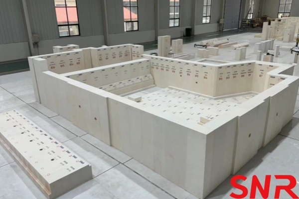
In the initial design stage of the furnace, consideration should be given to designing the depth of the refining section and the forehearth slightly shallower and the throat narrower. Literature studies indicate that such designs can effectively reduce glass melt recirculation in the refining section and forehearth, minimize secondary heating of the melt by the melter‘s energy, thereby not only lowering energy consumption but also improving the quality of the glass product.
Installing weirs in the melting and refining zones can both prevent unmelted batch material from the bottom layer of the melting end from entering the refining section, thus improving glass melt quality, and reduce the backflow of refined and homogenized melt from the bottom layer back to the melting end. This enhances bubble release velocity, increases melting rate, and improves glass melt quality.
During the furnace insulation construction phase, appropriate insulation materials should be matched according to the temperature requirements of each temperature zone to enhance insulation performance. Moreover, strict quality control must be enforced to ensure the insulation construction meets the design specifications. The heat dissipation from major parts such as the main crown, breast walls, burners, sidewalls, bottom, and the walls and arches of the regenerators accounts for over 80% of the total heat loss from the furnace structure. Therefore, implementing comprehensive, rational, and high-efficiency insulation and sealing on the glass melting furnace can not only significantly reduce heat loss from the furnace to the surroundings, maintaining stable internal temperature profiles and production process conditions, but also be conducive to increasing the melting rate. According to relevant data, adopting furnace insulation measures can reduce energy consumption by approximately 26%.

2.Rationality of Furnace Process Regime
The glass melting process occurs simultaneously at different locations within the furnace. The required heat input and temperature along the length of the melting furnace vary from zone to zone. To maintain normal melting operation, it is essential to ensure the heat supply and required temperature for each zone. Therefore, establishing a reasonable and stable temperature regime and rational fuel distribution is decisive for the melting process. The current trend in the load distribution among the furnace‘s port burners is to reduce energy input in the foam zone, enhance energy at the hot spot, with the batch blanket zone accounting for over 50% of the energy input.
The flue gas composition should be measured regularly above the regenerators. Based on the measured levels of O2 and CO in the flue gas and considering seasonal ambient temperature variations, the air-to-fuel ratio at the ports should be optimized and adjusted promptly. This aims to establish a reducing atmosphere in the batch blanket zone, an oxidizing to neutral atmosphere in the foam zone, and a strongly oxidizing atmosphere in the zone after the foam line. Typically, the oxygen (O2) content in the flue gas in the front zones should be controlled at no less than 1%, while in the rear zones it is advisable to control it between 2% and 3%, and not higher than 5% to avoid wasting natural gas and increasing energy consumption.
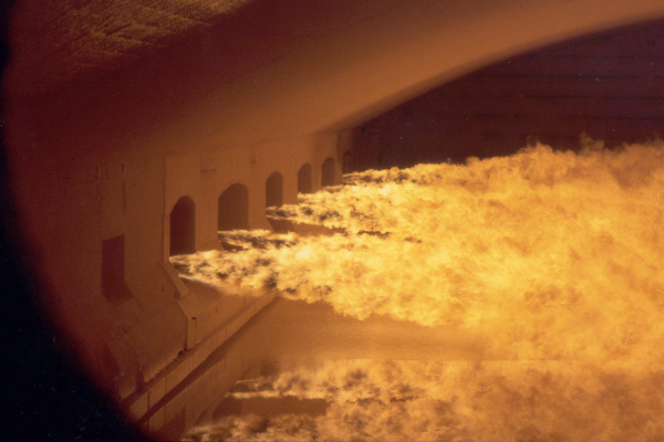
3.Burner and Flame Matching Control
The requirements for the flame inside the furnace can be summarized into five aspects: temperature, luminosity, length, angle, and rigidity (stiffness). The rationality of these "five aspects" depends not only on factors like combustion air volume and pressure but also crucially on the rational arrangement of the burners. In daily operation, appropriate burner nozzle and core diameters should be selected based on the fuel requirements of each port. During configuration, the matching between the burner‘s flow rate, spray angle, and the center distance of the nozzle blocks should be considered. The goal is to achieve flames that do not impinge on the batch pile in the batch area, flames as close as possible to the glass melt surface in the foam zone, and flames from the last port not touching the glass melt surface. A standardized burner cleaning procedure should be established to reduce the degradation of combustion efficiency caused by volatiles clogging the burner tips, thereby avoiding issues like increased energy consumption and reduced transmittance due to overly long, dull, or interfering flames.
The adjustment of the burner baffle plate‘s position relative to the burner and the burner block is also crucial. In daily production, the burner baffle plate should fit tightly against the burner and the burner block. This not only avoids the risk of flame escape but also reduces the ingress of cooling air from the baffle plate through gaps into the furnace, which would cause an increase in energy consumption.
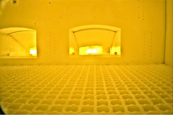
4.Periodic Regenerator Unblocking
During the melting of the batch, due to the entrainment of alkaline dust and the erosion by gases such as sulfur dioxide in the combustion exhaust, the regenerator checkerwork suffers dual damage from chemical and physical actions. This gradually degrades the surface of the checker bricks. High-temperature by-products with a certain viscosity flow down and condense into solids, blocking the checker flues at a temperature of approximately 850°C in the lower part of the regenerator checkerwork. This not only reduces process stability and leads to increased energy consumption but also significantly affects the furnace campaign life. Therefore, it is necessary to establish measures for periodic unblocking during furnace maintenance periods.
Regenerator unblocking can be performed in two ways. One is mechanical unblocking: during the air-in period, from below the lintel arch, using stainless steel unblocking rods to gradually impact, break up, and poke the blockages within the flues so they fall down. The other is heating-type unblocking: using specially designed burners to heat the checker flues from below upward, allowing the blockages to melt and flow down. Establishing and implementing a sound unblocking plan can achieve full fuel combustion, stable production processes, extended overall checkerwork life, and reduced furnace energy consumption.
5.Increasing Combustion Air Preheat Temperature
According to relevant data, for every 10°C increase in the preheat temperature of the combustion air, fuel savings of 0.7% to 0.8% can be achieved. The temperature of the combustion air has a significant impact on the furnace‘s energy consumption. The higher the combustion air temperature, the lower its cooling effect on the regenerator, and the higher the temperature of the air entering the furnace for combustion. Consequently, the furnace‘s energy consumption will be lower. In production, measures can be taken based on the specific conditions of the furnace to increase the combustion air preheat temperature, thereby improving natural gas combustion efficiency. Examples include changing the intake point of the combustion air fan, utilizing heat from the regenerator or the furnace structure itself to preheat the combustion air, and implementing measures related to doors, windows, and temperature management in the furnace area.
It is well known that fuel combustion requires oxygen participation. Under natural conditions, the oxygen content in air is approximately 21%. Most of the heat required in the glass production process is obtained through fuel combustion. Typically, the oxygen needed for fuel combustion is supplied by air. In air-assisted combustion processes, the nitrogen, which constitutes about 70% of the air, is detrimental and serves no useful purpose. A large amount of nitrogen is heated and then discharged into the atmosphere as waste gas (flue gas), resulting in significant heat loss.
If an oxygen-enriched combustion system is added to the furnace, considering the cost and specific consumption of producing oxygen-enriched gas, a purity of around 30% is generally sufficient. Due to the increased oxygen content in the combustion gas, fuel burns more completely, reducing fuel waste. The reduction in nitrogen decreases the volume of exhaust gas and the heat it carries away, thus improving thermal efficiency. The flame intensity is greater, and thermal radiation is stronger. According to relevant data, the energy-saving effect of oxygen-enriched combustion can reach about 10%.
Installing bubbling devices at the bottom of the batch charging area or the area before the hot spot, and introducing clean compressed air or inert gas (such as nitrogen) to form a uniform stream of bubbles at the bottom of the glass melt. Its energy-saving mechanism primarily lies in:
Enhanced Heat and Mass Transfer: The rising bubbles vigorously agitate the glass melt, promoting convection between the deep melt and the surface hot melt, accelerating batch melting and homogenization, which can improve thermal efficiency by 3%-5%.
Stabilizing the Foam Line: Helps in forming a clear foam line, reducing the amount of unmelted batch entering the refining zone, thereby lowering the extra fuel consumption required to refine this raw batch.
Reducing "Dead Zones": Prevents the formation of stagnant, low-temperature glass melt layers at the bottom, making full use of the tank depth, effectively increasing the melting rate.
Inserting electrodes into the bottom (or sidewalls) of specific areas in the charging end or melting end and applying auxiliary electrical power. Its energy-saving effects are reflected in:
Targeted Supplemental Heating: In areas where flame radiation heating is weak (especially in deep layers and areas covered by batch), direct and efficient volumetric heating is achieved through the glass melt‘s own resistance heating, precisely raising the temperature in those zones.
Increasing Pull Rate: While maintaining the same glass quality, it can significantly increase the furnace pull rate (up to 15%-30%), thereby reducing energy consumption per unit of product. It is particularly suitable for producing dark-colored glass or special glasses requiring high melting temperatures.
Stabilizing Operating Conditions: When the fuel system is insufficient or the furnace‘s melting capacity declines in its later campaign, electric boosting can serve as a stable supplemental heat source, ensuring production stability and avoiding energy consumption increases due to production reduction or temperature fluctuations.
9.Batch Pre-treatment and Optimization
Briquetting/Pellettizing and Preheating: Compressing powdered batch into dense briquettes or pellets can drastically reduce batch carryover loss during charging (by over 80%), minimizing both raw material waste and regenerator clogging. Further utilizing waste heat from flue gases to preheat the briquettes (up to 300°C or more) directly removes physical water and part of the chemically bound water, reducing the heat required for their vaporization inside the furnace. It is estimated this can save 8%-12% in energy.
Optimizing Batch Pile Shape ("Block Pile"): Changing the traditional long, strip-shaped batch pile into a denser, more uniformly edged "block pile" or "batch heap" reduces the surface area of the pile, lowering radiant heat loss. Simultaneously, it allows for more effective flame coverage and faster melting speed.
10.Deep Utilization of Waste Heat
After waste heat recovery by the regenerators, the flue gases still carry a significant amount of medium- to low-temperature heat. The following can be added:
Waste Heat Boilers (or Heat Pipe Exchangers): Produce steam for plant heating, cooling (via lithium bromide absorption chillers), or driving power generation units (Organic Rankine Cycle - ORC low-temperature power generation).
Batch and Fuel Preheating: As mentioned above, use the heat to preheat batch and fuel gas (natural gas), further increasing the initial enthalpy of materials and fuel entering the furnace.
11. Intelligent Control System
Establish an intelligent control system based on an advanced sensor network (monitoring temperature, pressure, atmosphere, images, etc.) and mathematical models (Computational Fluid Dynamics - CFD, heat transfer models).
Achieving Precise Control: Perform real-time dynamic optimization and closed-loop control of the temperature profile, air-to-fuel ratio, furnace pressure, glass level, etc., ensuring the furnace always operates under optimal conditions.
Predictive Energy Management: Use data analysis to predict trends in regenerator clogging, refractory erosion, etc., and schedule maintenance in advance to avoid sharp increases in energy consumption caused by deteriorating operating conditions.
Energy conservation and consumption reduction in glass furnaces are crucial for the sustainable development of the entire glass industry. Through means such as optimized design, selection of rational processes, control of process parameters, and full utilization of waste heat, the energy consumption of glass furnaces can be reduced, energy can be saved, and the goals of energy conservation and emission reduction can be achieved. Simultaneously, glass enterprises should also focus on technological innovation and management optimization to improve energy utilization efficiency, thereby enhancing both economic benefits and social benefits.
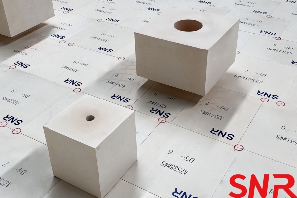
Henan SNR Refractory Co., Ltd. has been specializing in the production of fused cast AZS blocks for more than 25 years. We use high-quality raw materials and advanced fusion and casting technology and equipment to provide customers with high-quality products. From raw material procurement to finished product delivery, every step is strictly quality inspected to ensure that every indicator meets the standards, so you can use it with confidence.
Should you have any inquiries or specific requirements, our team is ready to provide professional support and tailored solutions.
 Contact Information:
Web: www.snr-azs.com
Email:wendy@snrefractory.com
 info@snr-azs.com
 +86-18203976036