
Glass melt leakage is one of the most serious safety accidents in glass furnace operations. It not only results in production losses but also poses a significant risk to personnel safety. This article begins by analyzing the erosion mechanisms of refractory materials, systematically examining the causes of glass melt leakage. It proposes a comprehensive multi-dimensional leakage prevention system from four perspectives: material selection and optimization, tank bottom and wall structural design, melting process control, and emergency response planning. This provides a reference for glass manufacturing enterprises to extend furnace campaign life and ensure production safety.
I. Introduction
II. Root Causes of Leakage: Erosion Mechanisms of Refractories
III. Design and Material Strategies for Leak Prevention
IV. Process Control and Maintenance During Operation
V. Emergency Response Plans
VI. Conclusion
I. Introduction
The glass melting furnace is the "heart" of glass production, and its operational status directly determines production efficiency and safety. A typical 500 t/d float glass furnace uses approximately 5,000 tons of refractory materials, representing a significant investment. However, operating under harsh conditions involving high temperatures (up to 1600°C), chemical attack, flame scour, and glass melt flow, refractories gradually degrade, with the most severe consequence being glass melt leakage.
Once a leak occurs, it can burn through the furnace‘s supporting steel structure, cause major equipment damage, and even lead to personal injury or fatality. Therefore, how to prevent glass melt leakage in furnaces is a core issue that must be addressed throughout the entire lifecycle, from design and construction to operation and maintenance. This paper will delve into this topic from four perspectives: materials science, structural design, process optimization, and emergency management.
II. Root Causes of Leakage: Erosion Mechanisms of Refractories
To prevent leakage, one must first understand how the glass melt breaches the refractory barriers.. The degradation of refractories is not caused by a single mechanism but results from the combined effects of chemical attack, physical erosion, and thermal stress.
1. Chemical Attack and the "Like Dissolves Like" Effect
The erosive power of glass melt towards refractories stems from its chemical composition. Conventional soda-lime glass belongs to the Na2O-CaO-SiO2 system, while refractories (like fused-cast AZS blocks) contain components such as Al2O3 and ZrO2. According to the "like dissolves like" principle, the high-temperature glass melt reacts with free SiO2 in the refractory, penetrating the block through pores and joints.
Alkaline oxides (especially Na2O) are the primary corrosive agents. They react with mullite and corundum in the refractory to form low-melting-point eutectic compounds, leading to structural loosening. Notably, the corrosive effect of sulfate (Na2SO4, often from salt cake) is even stronger than that of carbonate (Na2CO3).
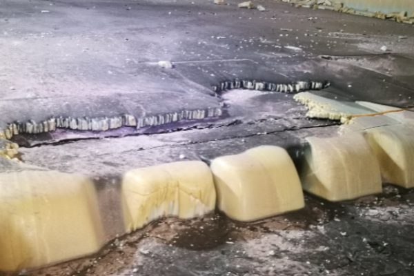
2. Physical Erosion and "Three-Phase Interface" Destruction
Near the glass melt level, a three-phase interface exists involving gas, liquid, and solid. Here, due to surface tension, the melt forms a meniscus, convection intensifies, creating a "vortex effect." This vortex continuously erodes the high-viscosity protective layer formed on the refractory surface by previous reactions, exposing fresh material to ongoing attack. This explains why the most severe wear on tank walls typically occurs in the zone approximately 300mm below the glass level.
3. Microstructural Defects
Pores (especially open pores) and joints within the refractory are direct pathways for melt penetration. The erosion process for fused-cast AZS blocks is often progressive: first, the glassy phase in the block is displaced by low-viscosity melt; then, the corundum phase dissolves; finally, un-melted baddeleyite crystals disperse, forming stones and causing structural disintegration.
III. Design and Material Strategies for Leak Prevention
Based on the mechanisms above, the first line of defense against leakage lies in upfront material selection and structural design.
1. Scientific Selection of Refractory Materials
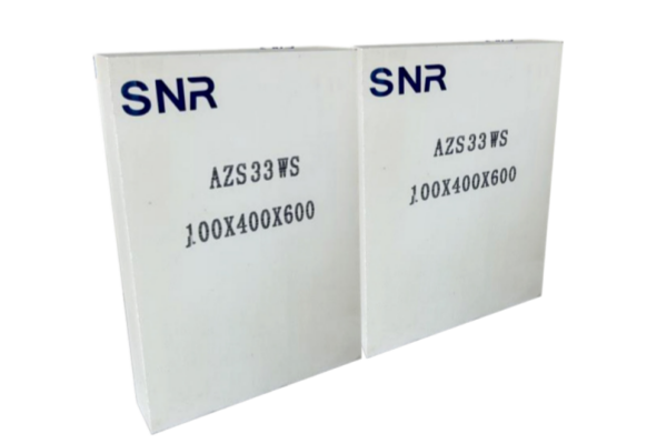
Application of High-Resistance Materials: In areas with severe erosion (e.g., tank walls at the glass level, throat, doghouse corners), materials with the highest corrosion resistance are mandatory. Refractories containing ZrO2 are the preferred choice. ZrO2 has extremely low solubility in silicate glasses, and its dissolution significantly increases the viscosity of the boundary layer melt, slowing down the erosion rate. For fused-cast AZS blocks, oxidation-melted, void-free cast blocks should be prioritized. Oxidation-melted 33# AZS blocks have a glassy phase exudation temperature above 1400°C, whereas reduced-melted products are only around 1080°C, resulting in a significant performance gap.
Systematic Matching: Follow the principle of "high-quality materials for vulnerable areas, standard materials for others" to achieve "balanced campaign life." For example, the deep layers of the tank wall can use dense fused-cast AZS, while the bottom layers of the tank bottom might use fireclay bricks, but this must be combined with a perfect sealing layer system.


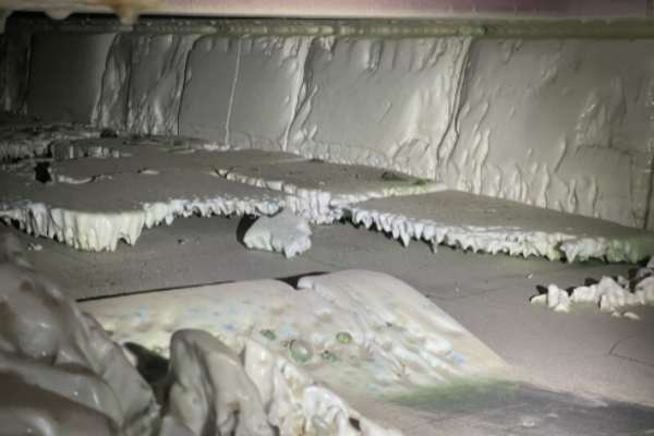
2. Leak-Proof Design of the Tank Bottom
Bottom leaks are the most hazardous type, often caused by "upward drilling" of the melt or "downward drilling" by metallic particles.
Multi-Layer Sealing Technology: Modern tank bottom structures typically employ multiple protective layers. Between the paving block (fused-cast AZS) and the bottom backup block, a dense sealing layer must be installed. Using fused-cast AZS ramming mix, whose crystalline phase matches the paving block, as the sealing layer and joint filler allows it to sinter into a monolithic mass at around 1250°C. The mechanism is: between 800-1100°C, the glassy phase in the ramming mix sinters and exhibits plasticity, adhering well to the blocks; above 1200°C, the ramming mix devitrifies and becomes a hard, corrosion-resistant composite layer.
Prevention of Metallic Drilling: Metallic impurities (e.g., iron scraps) entering with the batch can settle on the bottom, react with the refractory at high temperatures, form low-melting phases, and drill downwards rapidly. To counter this, a zircon brick layer can be installed beneath the bottom sealing layer. Zircon reacts with the melt to form a highly viscous zirconium-containing silicate material that can encapsulate penetrating metals, preventing further downward drilling.
3. Optimization of Tank Wall Structure
Use of Large Blocks with Vertical Joints: Tank walls should be constructed using large, monolithic blocks laid vertically. Horizontal laying is strictly forbidden because horizontal joints erode much faster than vertical ones. During construction, joints must be minimized (typically <1mm) and surfaces kept smooth to reduce melt stagnation and attack points.
Provision for Future "Blind Tuck" (Patching): The design phase should anticipate the later need for "blind tucking" (applying a new layer of blocks on the outside after the inner wall has thinned). Space for blind tucking and positions for cooling air installations should be reserved in the furnace steel structure design from the beginning to facilitate mid-to-late campaign maintenance.
IV. Process Control and Maintenance During Operation
Even the best materials will degrade faster if improperly operated. Scientific process control forms the dynamic line of defense against leakage.
1. Key Control Points in Melting Operations
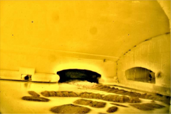
Batch Pile Management: An offset batch pile clinging to the tank wall is a primary cause of localized rapid wear. Due to transverse temperature differences in the furnace (lower temperatures near sidewalls compared to the center), resulting transverse convection currents can draw the batch pile towards the walls, forming an "inverted V-shaped" erosion pattern.
Control measures include: Adjusting charger gate to create a batch layer distribution that is "thicker in the middle, thinner at the edges" to match the temperature field; maintaining temperature symmetry across the furnace by ensuring consistent heat input, flame length, and regenerator flowability on both sides.
Glass Level Stability: Fluctuations in the glass level expand the erosion zone, leaving "froth marks" on the tank walls. The stability of the pull rate must be strictly controlled to minimize level fluctuations during operations like firing reversal or color changes. Typically, level fluctuations should be kept within ±0.2 mm.
Temperature Regime: An increase in melting temperature of 50-60°C can potentially shorten the service life of refractories by approximately one year. While meeting melting quality requirements, unnecessary high temperatures should be avoided. Especially in the later furnace campaign, reducing the power of electric boosting or adjusting the gas-to-air ratio can lower the surface temperature of electrode blocks and surrounding bottom refractories.
2. Forced Cooling Protection
Tank Wall Air Cooling: Air cooling of the tank wall is one of the most direct and effective ways to extend its life. By forcing air across the outside of the wall (approximately 100mm below the glass line), the hot face temperature of the refractory is lowered, slowing down the chemical reaction rate.
Control key points: Early in the campaign when the wall is thick (>200mm), the air volume can be relatively low (e.g., 40% of maximum capacity). Mid-campaign, as the wall thins to <200mm, the air volume should be increased to 60-80%. In the late campaign, full capacity should be used. The principle is to "increase or decrease gradually" to avoid thermal shock cracking. Visual observation (no red glow at night) or infrared temperature measurement indicating appropriate temperatures signifies adequate cooling.
Water Cooling Assistance: For areas with locally severe thinning, L-shaped cooling hooks can be applied inside the tank wall. This cools the block and alters the melt flow pattern locally. However, water cooling is a double-edged sword and can exacerbate local thermal gradients, requiring careful use.
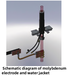
Tank Bottom Cooling: For vulnerable points like electrode blocks or bubbler blocks, cooling devices can be installed underneath the bottom to prevent leakage. If a leak occurs, the cooling medium in the device can quickly solidify the escaping melt, preventing escalation.
3. Daily Inspection and Monitoring
Infrared Thermography: Regularly scan the furnace shell using an infrared thermal imaging camera. An abnormally high temperature ("hot spot") on the outside of a tank wall usually indicates severe internal thinning, signaling a potential leak risk.
Residual Thickness Assessment: Combine furnace operating age with empirical formula for erosion rates to periodically assess the remaining thickness of key areas, planning for blind tucking or hot repairs.
V. Emergency Response Plans
Despite comprehensive prevention, oversights can still lead to leaks. A well-defined, scientifically sound emergency plan is the final barrier preventing a minor leak from becoming a major disaster.
Note: Water application should start gradually to avoid thermal shock cracking of surrounding blocks.
2. Post-Incident Handling
After the leak point has been solidified and sealed, refractory masons must professionally treat the affected area (e.g., by cutting out damaged blocks and blind tucking). Following the repair, the glass level and temperature must be raised back to normal very slowly (e.g., 1-2 mm/h for the level), and the area should be subjected to enhanced inspection.
3. Emergency Response for Special Situations
Bottom Cooling Failure: If the combustion air fan, furnace crown cooling fan, or tank wall cooling fan stops, immediately start the backup fan to prevent localized overheating and melting due to loss cooling.
Cooling Equipment Water Leakage: If a water-cooled device like a "doghouse" canal barrier or stirrer springs a leak, immediately assess the severity. If serious, rapidly remove the equipment from the furnace and shut off its water supply to prevent large amounts of water entering the furnace, which could cause a violent reaction or explosion. Simultaneously, alert the forming department to prepare for potential temperature fluctuations.
VI. Conclusion
Preventing glass melt leakage in furnaces is a systematic engineering. It begins with scientific material selection during design, depends on the meticulous pursuit of perfect joints and sealing during construction, centers on the precise control of temperature, glass level, and batch piles during operation, and concludes with a calm, scientific, and swift emergency response to unexpected situations.
With advancements in material characterization (e.g., in-situ high-temperature microscopy) and the development of intelligent furnace management systems, the future holds the potential to further minimize leakage risks through real-time monitoring of erosion and dynamic adjustment of operating parameters. For today‘s glass manufacturers, respecting scientific principles, understanding degradation mechanisms, and finding the optimal balance between cost and longevity through precision inspection and systemic design are the only ways to truly safeguard this "flowing line of molten life."
Henan SNR Refractory Co., Ltd. has been specializing in the production of fused cast AZS blocks for more than 25 years. We use high-quality raw materials and advanced fusion and casting technology and equipment to provide customers with high-quality products. From raw material procurement to finished product delivery, every step is strictly quality inspected to ensure that every indicator meets the standards, so you can use it with confidence.
Should you have any inquiries or specific requirements, our team is ready to provide professional support and tailored solutions.
 Contact Information:
Web: www.snr-azs.com
Email:wendy@snrefractory.com
 info@snr-azs.com
 +86-18203976036