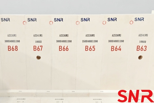
As the core device of glass production, extending the life of the glass furnace has always been a concern for glass producers. The sidewall of the glass furnace is the most critical part, and the degree of erosion directly affects the service life of the glass furnace. To protect the sidewall of the glass furnace, it is essential to first understand why the sidewall is eroded.
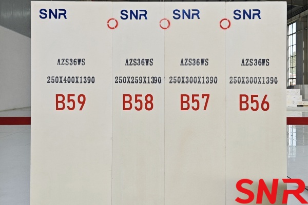
1. Reasons for Erosion of the Glass Furnace Sidewall
(1) Material Interaction: During glass production, the materials in the glass furnace are heated by high-temperature radiation from the flame as they move longitudinally through the furnace. The first stage involves the silicate reaction between the various components of the raw materials. The second stage consists of unreacted foamy silicate ballast, and the third stage sees the gradual melting into the glass liquid. Sodium oxide intrudes into the interior by penetration and diffusion from the glass phase and pores of the sidewall blocks. The protective layer is lost under the action of glass liquid temperature erosion and the scouring effect of the glass liquid flow. This is the main factor contributing to sidewall erosion.
(2) Temperature Differences: Due to the existence of horizontal and vertical temperature differences in the glass furnace, the glass liquid appears calm under the surface, but in reality, there are various intricate horizontal and vertical convection currents. The chemical zone, the foam zone, and the clear glass liquid zone are not only heated by the flame but also by the circulating molten glass liquid stream. These diverse convection currents promote the melting, clarification, and homogenization of the glass but also contribute to the erosion of the sidewalls.
(3) Erosion Hot spots: From practical experience in glass furnace production, the area from the glass liquid surface line to about 300 mm below is particularly susceptible to severe erosion due to the low viscosity and high flow rate of the glass liquid. The most severe erosion occurs at the gas, liquid, and solid three-phase junction in the chemical material area of the sidewall, rather than at the gas-liquid two-phase junction at the highest temperature hot spot of the furnace sidewall. Therefore, the pile of material close to the sidewall is also most likely to cause scouring erosion.
(4) Cooling Measures: Generally, glass furnaces employ air cooling measures to protect the sidewalls. Air is blown from the outer side of the sidewall about 100 mm below the liquid surface to lower the internal temperature of the sidewall blocks locally, thereby slowing down the erosion caused by the pile of material and the glass liquid. The sidewall cooling air plays a crucial role in extending the life of the sidewall. If the blowing position is unreasonable, or the blowing is too weak, it cannot fully utilize the cooling effect, leading to accelerated erosion of the sidewall blocks. Unstable control of the sidewall cooling air can cause thermal shocks and cracks in the sidewall blocks.
(5) Operational Factors: Currently, most float glass manufacturers use a ‘double high heat load‘ glass melting system, which increases the temperature of the 1# to 2# small glass furnaces, resulting in higher doghouse temperatures and more active bottom piles. Due to the melting operation, the temperatures on both sides of the sidewall are lower than the temperature in the middle of the glass furnace, causing the lateral convection of the glass liquid to push the pile forward toward the sidewall. Additionally, most large float glass furnaces use more than two sets of inclined blanket charging machines, and each stock cannot be individually adjusted in terms of direction, which over time leads to the formation of an ‘inverted V-shaped‘ pile skewed toward the sidewalls. This skewed pile directly adjacent to the material area of the port sidewall blocks forward and gradually melts, producing a significant scouring effect and accelerating the erosion rate of the sidewall blocks in the material area.
2. Maintenance Measures for the Sidewall in a Glass Furnace
(1) Sidewall Cooling Air Control
① During glass furnace production, it is crucial to determine the correct sidewall cooling air blowing position and width. The blowing position should be adjusted daily based on production conditions. The optimal blowing position is approximately 100 mm below the glass liquid surface. The blowing nozzle should have a sufficient width to ensure the cooling air covers a width of about 60–80 mm on the sidewall, thereby increasing the cooling protection area of the sidewall blocks.
② Ensure the stability of the sidewall cooling air volume and blowing intensity. The appropriate air volume can be determined by observing whether the sidewall tiles glow red at night or by using an infrared thermometer to measure the outer surface temperature of the sidewall. The blowing intensity should be adjusted so that the air rebounding from the sidewall tiles can be felt when standing in the port aisle.
③ When increasing the sidewall cooling air volume during normal production, it should be done gradually in several increments to prevent rapid cooling and cracking of the sidewall.
④ Adjust the sidewall air volume according to the actual condition of the glass furnace at different stages. In the initial stage of the glass furnace (when the sidewall thickness is greater than 200 mm and the furnace has been in operation for about 1 year), the air volume can be set lower, at approximately 40% of the total sidewall air volume. During the middle stage of the glass furnace operation (when the sidewall thickness is less than 200 mm), the air volume should be increased to 60%–80% of the total sidewall air volume. In the late stage of the glass furnace (when the sidewall blocks in the chemical material area and hot spots have been significantly eroded), the sidewall air volume should be fully opened.
(2) Control of the Material Pile
① During the feeding operation, adjust the thickness of the material layer by regulating the gate opening of the feeding machine. This ensures that the material pile discharged from the feeding machine forms a thicker layer in the middle of the glass furnace and gradually thins toward the sidewalls on both sides. This adjustment aligns with the actual lateral temperature distribution characteristics of the glass furnace, where the glass liquid temperature is higher in the middle (requiring a thicker material layer) and lower near the sidewalls (requiring a thinner material layer). This approach ensures uniform material distribution, improves material efficiency, and effectively reduces the temperature difference between the middle of the glass furnace and the sidewalls. It also minimizes lateral convection in the glass furnace, preventing the material pile from contacting the sidewalls. As a result, the temperature on both sides of the glass furnace tends to equalize, creating a positive cycle.
② Maintain temperature symmetry on both sides of the glass furnace during temperature control. This can be achieved by:
► Ensuring the heat load on both sides remains the same.
► Keeping the heat storage chamber‘s lattice body unobstructed.
► Maintaining the same gate opening for the branch flues on both sides.
► Ensuring the flame length and rigidity of the burners on both sides are relatively consistent.
These measures help minimize the lateral temperature differences caused by temperature control during the melting operation, preventing the material pile from skewing.
(3) Liquid level control
“Stable liquid level” is an effective guarantee for protecting the sidewall. During the glass production process, the pulling amount should be kept relatively stable to reduce the ups and downs of the glass liquid level and reduce the erosion of the sidewall by the fluctuation of the glass liquid level.
(4) Technical Remedial Measures to Prevent Material Skewing and Protect the Sidewall
① Central Solid Material Cooling Water Pipe
A cooling water pipe with a diameter of 76 mm and a length of approximately 7–8 meters is installed at the center of the glass furnace, between the two charging machines. The pipe is placed close to the material surface and extends to around the position of the 2# port. By utilizing the heat absorption and cooling effect of the cooling water pipe, the material piles on both sides are attracted to move forward along the pipe, preventing them from leaning against the sidewalls. This results in an increase in the temperature of the glass liquid near the sidewalls. When the temperature difference between the center and the sides of the glass furnace is reduced, and lateral convection reaches equilibrium, the material pile becomes stable and does not skew. This method effectively prevents material skewing, reduces sidewall erosion, and improves glass quality.
② Sidewall Material-Blocking Water Pipes
In cases where an "inverted V-shaped" material pile forms due to specific glass furnace conditions and cannot be easily corrected during the melting operation, a material-blocking water pipe can be installed on each side of the charging area. Each pipe, with a diameter of 76 mm and a length of 7–8 meters, is placed close to the glass liquid surface and tilted slightly toward the center of the furnace. Within the effective length of the blocking water pipes, the skewed material pile is forcibly redirected, altering its movement path and reducing its contact with the sidewalls near the melting zone. This helps mitigate the scouring effect of the material pile on the sidewalls.
③ Sidewall Cooling Water Hooks
As the sidewalls are continuously eroded by scouring, some manufacturers install cooling water hooks from the bottom gap blocks when the sidewall thickness in the melting zone becomes relatively thin (around 100 mm) after a certain period of furnace operation. Typically, 2–3 cooling water hooks are installed for each port sidewall. These L-shaped hooks, with a length of 800–1000 mm, are placed tightly against the inner side of the sidewall and extend 60–70 mm into the material layer, depending on the height of the bottom gap blocks. The cooling water hooks prevent the skewed material pile from pressing against the sidewall and reduce the viscosity of the glass liquid in that area, thereby slowing down the erosion rate of the sidewall. However, cooling water hooks are a double-edged sword. While they protect the sidewall, their cooling effect increases the temperature difference between the center and the sides of the glass furnace, making the material pile more prone to skewing.
To address this issue, cooling water hooks can be used in combination with material-blocking water pipes. This approach not only reduces the viscosity of the glass liquid near the sidewall and minimizes erosion but also forcibly redirects the material pile, counteracting the skewing tendency caused by the cooling water hooks. As a result, the material pile no longer tightly scours the sidewall, providing better sidewall protection.
④ Sidewall Block Binding
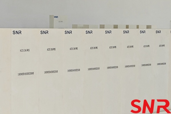
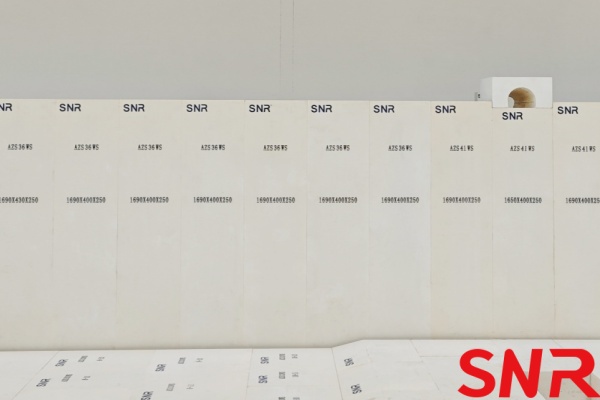
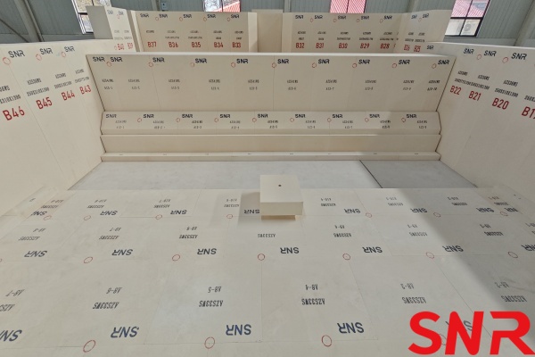
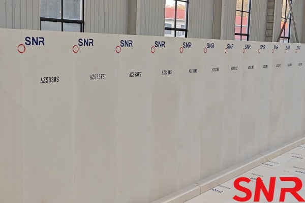
In the middle to late stages of the glass furnace campaign, when the sidewall thickness becomes significantly reduced, sidewall block binding can be employed. This involves using 33# or 36# oxidation-bonded, non-shrinkage fused cast AZS blocks with dimensions of 300 mm × 400 mm × 100 mm. The blocks are bound from the 1# port to the sidewall near the hot spot port. Each binding operation, combined with an appropriate increase in sidewall cooling air, can generally ensure safe operation for about 2 years. Typically, block binding can be performed twice within a single glass furnace campaign.
At the same time, in the selection of materials for glass furnace sidewall blocks, high temperature tolerance, corrosion resistance and thermal shock stability must be comprehensively considered. Commonly used materials include:
♦Fused cast AZS blocks (such as 33#, 36#, 41#. The higher the ZrO2 content, the stronger the corrosion resistance. It is suitable for key parts such as melting end and throat)
♦Fused corundum bricks (α-β Al2O3 bricks, resistant to alkali steam corrosion, suitable for the upper part of the glass furnace or cost-sensitive areas)
♦Sintered zircon bricks (ZrSiO4 bricks, resistant to thermal shock but easy to decompose at high temperature, suitable for medium and low temperature glass furnaces)
♦Chrome corundum bricks (Al2O3-Cr2O3bricks, resistant to erosion by special glasses such as fluorine and lead, but attention should be paid to environmental protection issues)
♦Quartz bricks (SiO2 bricks, acid-resistant but not alkali-resistant, mostly used in small glass furnaces).
The actual selection needs to be optimized according to the glass composition (such as soda-lime glass, borosilicate glass, etc.), glass furnace temperature and process conditions. Usually, high-zirconium AZS blocks are preferred in high-temperature corrosion areas, and alkali vapor-enriched areas can be matched with fused cast AZS blocks, and air cooling/water cooling protection can be used to extend the service life.
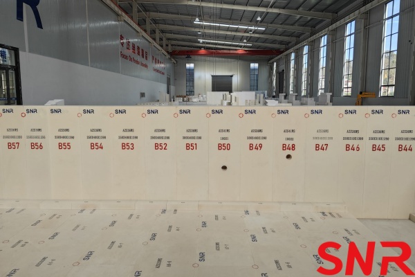

Henan SNR Refractory Co., Ltd. is dedicated to the manufacturing research and development of fused cast AZS refractory materials for the glass industry. Meanwhile, SNR can provide total solutions and services for glass furnace design, glass furnace construction, renovation, and upgrading. Please contact me if you have any requirements.
CONTACT: zoe@snrefractory.com
WEBSITE: www.snr-azs.com


