
As a complex high-temperature thermal system, a glass furnace exhibits significant differences in thermal load, chemical attack, mechanical erosion, and atmosphere conditions across various zones. Fused cast AZS refractories serve as the “skeleton” of glass furnaces. The proper selection of grades (AZS 33#block, AZS 36#block, and AZS 41#block) directly determines the glass furnace campaign life, glass melt quality, and overall construction cost. Starting from the differences in chemical composition, mineralogical phases, microstructure, and macroscopic physical properties of the three materials, and combined with the corrosion mechanisms of glass melt on refractories, this paper systematically discusses their differentiated application strategies in key areas such as sidewalls, throat, superstructure, and doghouse. Furthermore, it deeply analyzes technical details such as casting method selection, glass phase exudation control, and jointing mortar compatibility, along with simulation technologies and future trends, aiming to provide systematic theoretical basis and practical guidance for achieving “balanced wear” and “cost optimization” throughout the glass furnace.
1. Cornerstone Status of Fused Cast AZS Blocks in the Glass Industry
1.1 Requirements for Glass Furnace Refractories Driven by Glass Industry Development
As the global glass manufacturing industry advances toward high output, premium quality, low consumption, and extended service life, glass furnaces—the core equipment in production lines—are required to have campaign lives typically ranging from 8 to 12 years, with some advanced glass furnaces even pursuing more than 15 years. Under such circumstances, fused cast refractories, particularly fused cast alumina-zirconia-silica (AZS) blocks, serve as the first line of defense against corrosion by high-temperature glass melt, ensuring structural integrity of the glass furnace.
The internal environment of a glass furnace is extremely harsh: melting temperatures can exceed 1600 °C, the glass melt is strongly alkaline, alkali vapor concentration is high, melt flow erosion is intense, and temperature fluctuates periodically. Under these conditions, refractories must not only possess excellent corrosion resistance but also exhibit good thermal shock resistance, erosion resistance, low contamination of the glass melt, and economic viability. Fused cast AZS blocks, by virtue of their unique microstructure and superior overall performance, occupy an irreplaceable position in critical zones of glass furnaces.
1.2 Manufacturing Process and Classification of Fused Cast AZS Blocks
Fused cast AZS blocks (Alumina-Zirconia-Silica) are produced by batching high-purity alumina, zirconia, and silica, melting the mixture in an electric arc furnace at temperatures exceeding 2000 °C, casting into molds, and then subjecting the castings to a rigorous annealing process to eliminate internal stresses. The manufacturing process includes five main steps: batching, melting, casting, annealing, and finishing, each significantly impacting the final product quality.
According to the Chinese building materials industry standard JC/T 493-2015 and related international standards, they are classified into three main grades based on zirconia (ZrO₂) content:
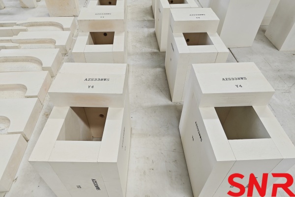
AZS 33#block: ZrO₂ content approx. 33%, Al₂O₃ approx. 50%, SiO₂ approx. 15%.
AZS 36#block: ZrO₂ content approx. 36%, Al₂O₃ approx. 48%, SiO₂ approx. 14%.
AZS 41#block: ZrO₂ content approx. 41%, Al₂O₃ approx. 45%, SiO₂ approx. 12%.
Among these, zirconia is the core component determining corrosion resistance, alumina provides structural strength, while silica primarily resides in the glass phase, affecting sintering and forming characteristics.
1.3 Current Misconceptions and Challenges in Material Selection
For a long time, many glass enterprises have exhibited two typical misconceptions in material selection:
First, the “higher-grade-is-better” fallacy. Believing that a higher grade always delivers better performance, they blindly pursue AZS 41#block—the highest ZrO₂ content—in critical zones, or even use AZS 41#block throughout the entire glass furnace. This practice leads to substantially increased initial investment, resulting in significant “over-engineering”. Statistics indicate that all-AZS 41#block schemes raise initial investment by 40%–50% compared to hybrid schemes, without proportionally extending glass furnace life.
Second, the “one-size-fits-all” strategy. Using the same grade throughout the glass furnace ignores variations in operating conditions across different zones. This approach can lead to two outcomes: if a lower grade is used, localized premature wear shortens glass furnace life; if a higher grade is used, performance is wasted in areas where corrosion is mild.
Therefore, scientifically combining these three grades based on the chemical corrosion mechanisms and physical wear characteristics of different zones—achieving “balanced wear”—is the key to balancing glass furnace economy and longevity. “Balanced wear” means rationally allocating materials with different performance levels so that the theoretical service lives of all major glass furnace sections converge, preventing the entire glass furnace from being retired prematurely due to localized failure.
2. Core Differences Among AZS 33#block, AZS 36#block, and AZS 41#block
To formulate a scientific application strategy, it is essential to thoroughly understand the essential differences in microstructure and macroscopic properties of these three materials. This chapter provides a systematic comparison across chemical composition, mineral phases, microstructure, key physical properties, and corrosion mechanisms.
2.1 Chemical Composition and Mineral Phases
The performance of AZS blocks is primarily determined by their chemical composition and mineral phase distribution. Table 1 compares the nominal chemical composition and typical mineral phases of the three grades.
|
Grade |
ZrO₂ (%) |
Al₂O₃ (%) |
SiO₂ (%) |
Baddeleyite (%) |
Corundum (%) |
Glass Phase (%) |
|
AZS 33#block |
33 |
50 |
15 |
~30 |
~45 |
20–25 |
|
AZS 36#block |
36 |
48 |
14 |
~35 |
~43 |
18–22 |
|
AZS 41#block |
41 |
45 |
12 |
~42 |
~40 |
12–15 |
♦AZS 33#block: ZrO₂ content: 33%. Its mineral phases mainly consist of eutectic crystals (corundum + zircon) and a glass phase. Because ZrO₂ content is relatively low, the proportion of corundum (α-Al₂O₃) is higher, and the glass phase content is typically 20%–25%. This structure gives it good thermal shock resistance but relatively limited corrosion resistance in high-temperature glass melt. The glass phase has higher Na₂O content and a lower exudation temperature.
♦AZS 36#block: ZrO₂ content: 36%. As ZrO₂ proportion increases, baddeleyite (ZrO₂ crystals) begins to increase notably, forming an initial skeletal structure, and glass phase content slightly decreases to 18%–22%. It lies in the transition zone between AZS 33#block and AZS 41#block, combining decent corrosion resistance with moderate cost. Microstructurally, baddeleyite crystals are distributed dendritically, interlocking with corundum to form a relatively dense structure.
♦AZS 41#block: ZrO₂ content: 41%, representing the upper limit of ZrO₂ content in fused cast AZS blocks. Its microstructure consists of a dense skeleton formed by abundant baddeleyite crystals, with corundum filling the gaps. Baddeleyite crystals are lath- or columnar-shaped, mutually interlocking to create an “interlocking” structure. With ZrO₂ melting point as high as 2700 °C and extremely strong chemical stability, the block exhibits outstanding corrosion resistance against glass melt. Its glass phase content is the lowest, typically controlled below 15%, and the glass phase composition is optimized to have higher viscosity and higher exudation temperature.
2.2 Microstructural Characteristics and Formation Mechanisms
The microstructural differences among the three grades mainly originate from the varying ZrO₂ content. During cooling after fusion, ZrO₂ crystallizes first to form baddeleyite crystals. When ZrO₂ content is low, baddeleyite crystals are isolated; as ZrO₂ content increases, the crystals become more numerous and interconnect; when ZrO₂ content reaches about 41%, a continuous crystal skeleton forms.
The glass phase fills the interstitial spaces during cooling. The content and composition of the glass phase directly affect the material’s high-temperature performance: higher glass phase content yields better thermal shock resistance but poorer corrosion resistance; lower glass phase content enhances corrosion resistance but increases brittleness and reduces thermal shock resistance.
2.3 Comparison of Key Physical Properties
2.3.1 Corrosion Resistance to Glass Melt
This is the most critical performance indicator. In soda-lime glass melt at 1500–1600 °C, taking the corrosion rate of AZS 33#block as 1.0, that of AZS 36#block is approximately 0.7–0.8, while AZS 41#block is as low as 0.4–0.5.
The difference in corrosion rates stems from the extremely low solubility of ZrO₂ in glass melt. When an AZS block contacts glass melt, the melt preferentially dissolves the glass phase and corundum, while baddeleyite crystals remain virtually unattacked. As corrosion progresses, a “reaction layer” enriched with baddeleyite crystals forms near the hot face; this dense layer effectively inhibits further penetration and chemical dissolution by the glass melt. Higher ZrO₂ content results in a denser and more protective reaction layer.
2.3.2 High-Temperature Modulus of Rupture
AZS 41#block, due to its dense baddeleyite skeleton, exhibits the highest high-temperature modulus of rupture. Test data show that at 1400 °C, AZS 33#block has a modulus of rupture around 8–10 MPa, AZS 36#block around 10–12 MPa, and AZS 41#block can reach 12–15 MPa. The advantage of high strength is particularly prominent in areas subjected to high-velocity glass melt flow, such as the throat and around electrodes.
2.3.3 Thermal Shock Resistance
Thermal shock resistance is a weakness of AZS blocks and is negatively correlated with ZrO₂ content. AZS 33#block, with its higher glass phase content and relatively uniform thermal expansion, has the best thermal shock resistance; AZS 41#block, due to the larger difference in thermal expansion between baddeleyite and corundum and more internal microcracks, has the poorest thermal shock resistance. Therefore, high-grade blocks should be avoided in areas with severe temperature fluctuations (e.g., doghouse).
2.3.4 Foaming Tendency and Glass Phase Exudation Temperature
This is a key factor affecting glass quality. The glass phase in AZS blocks can soften at high temperatures and may exude, reacting with the glass melt to form stones or stripe.
AZS 33#block: glass phase exudation temperature is relatively low (approx. 1200–1250 °C), exudation amount is manageable, and the exudate has low viscosity, making it easily assimilated by the glass melt.
AZS 41#block: although the glass phase is less, the residual glass phase composition has high viscosity and a higher exudation temperature (approx. 1350–1400 °C). Moreover, due to the dense casting, the exudate is more difficult to diffuse. If annealing is inadequate, it may accumulate on the hot face and spall during temperature fluctuations, forming “zirconia-corundum” stones.
2.3.5 Risk of Contamination to Glass Melt
High-grade blocks, having less glass phase and stable baddeleyite crystals, theoretically diffuse fewer zircon decomposition products into the glass melt, implying higher purity. However, this advantage presupposes that the casting is dense, crack-free, and well-annealed. If internal defects exist, local spalling may actually cause more severe contamination.
3. Corrosion Mechanisms and Material Matching for Different Glass Furnace Zones
Glass furnaces can be broadly divided into the melting zone (hot spot, bottom, sidewalls), working flow zone (throat), superstructure (breastwalls, crown, port necks), and doghouse. Each zone has distinct temperature, atmosphere, glass melt flow velocity, and alkali vapor concentration, requiring material selection tailored to local conditions.
3.1 Melting Zone – The Main Battlefield of High-Temperature Glass Melt
3.1.1 Sidewall Blocks: Application of Three-Line Corrosion Theory
Sidewalls endure vertical cutting by static glass melt at high temperatures. Based on glass melt convection models and long-term practical experience, sidewalls exhibit “three-line wear”: glass line wear, gas interface wear, and convection current wear.
Glass line (metal line): This is a “three-phase interface” (glass melt, refractory, glass furnace atmosphere) where corrosion is most severe. Condensation and reflux of alkali vapor create an “alkali waterfall,” reacting with the block to form low-melting phases such as nepheline (Na₂O·Al₂O₃·2SiO₂), causing “necking.” The corrosion rate at the glass line is typically 2–3 times that of areas below the melt line. Severe cases can lead to block fracture and glass leakage, making it the primary constraint on glass furnace life.
Gas interface zone: The region approximately 200 mm above the glass line is directly scoured by alkali vapor and flame. Alkali vapor penetrates into block pores, reacting with the glass phase and corundum to form low-melting compounds, causing structural spalling.
Convection current zone: From the glass line down to the bottom, erosion is mainly driven by glass melt convection. In the hot spot region, melt flows upward; near the doghouse, it flows downward. Convection velocities can reach several meters per hour, causing continuous mechanical wear on the block surface.
Application Strategy:
►Glass line region: For large high-quality float glass furnaces or high-borosilicate glass furnaces, AZS 41#block (or 41# void-free blocks with tilt casting) should be the first choice in the 300 mm zone around the glass line. Its high corrosion resistance maximally delays glass line wear, preventing thinning and leakage risks.
►Main sidewall zone: Below the glass line down to the bubbling zone, AZS 36#block is recommended. Although temperatures are high in this area, there is no direct alkali vapor attack, and the corrosion resistance of AZS 36#block is adequate, while its cost is lower than that of AZS 41#block.
►Bottom region: Near the glass furnace bottom where glass melt convection is weak, AZS 33#block meets requirements.
3.1.2 Bottom Paving Tiles and Corner Blocks
The glass furnace bottom is primarily subjected to the weight of glass melt and bottom convection. With the widespread adoption of electric boosting, bottom temperatures rise and convection intensifies. Particularly around electrodes, localized high temperatures and electromagnetic stirring effects exacerbate erosion.
Application Strategy:
►Corner blocks: At the connection between sidewall and bottom, structural stress concentrates and glass melt flow creates vortices with severe erosion. It is recommended to use AZS 36#block or AZS 41#block to ensure structural strength and erosion resistance.
►Paving tiles: For ordinary soda-lime glass, AZS 33#block is sufficient; for alkali-free glass fiber or high-alumina glass, due to higher viscosity and temperature, upgrading to AZS 36#block is recommended to prevent “hollowing out” or localized depressions.
►Around electrodes: Electrode blocks and surrounding areas should use AZS 41# Void-Free grade to ensure long-term stability under electric boosting conditions.
3.2 Throat – The “Throat” of the Glass Furnace
The throat connects the melting tank to the working tank, and all glass melt passes through it. Here, glass melt velocity is extremely high (often dozens of meters per day), temperatures are elevated, and intense mechanical erosion occurs. The throat typically has small dimensions (width approx. 300–500 mm, height approx. 200–300 mm), resulting in high mass flow per unit area.
Corrosion characteristics: Primarily wear and erosion, supplemented by chemical dissolution. The corrosion rate in the throat can be 2–3 times that of the sidewalls. Once the throat enlarges, the pressure differential between melting and working tanks disappears, causing glass melt short-circuiting, and the glass furnace life ends. Throat failure is one of the leading causes of glass furnace retirement.
Application Strategy:
►Mandatory AZS 41#block: Whether for cover blocks, side blocks, or bottom blocks, the throat must use 100% AZS 41#block, and it must be void-free cast or dense cast . Any pores or shrinkage cavities here become starting points for accelerated erosion.
►Cooling assistance: Even with AZS 41#block, the throat usually requires forced air cooling to keep the hot face temperature below 1500 °C, ensuring long-term stability.
►Structural design: The throat configuration (horizontal, inclined, or submerged) also influences corrosion rates and should be optimized alongside material selection.
3.3 Superstructure (Breastwalls, Crown, Port Necks) – Ravaged by Alkali Vapor
The superstructure does not contact glass melt directly but suffers high-temperature chemical attack from alkali vapor and batch dust. Alkali vapor primarily comes from Na₂O volatilized from the glass melt surface, combining with combustion products in the upper glass furnace space to form a strongly alkaline atmosphere.
Corrosion characteristics: Alkali vapor (Na₂O, K₂O) condenses and penetrates into block pores, reacting with the glass phase and corundum to form low-melting phases such as nepheline and feldspar (melting points around 1000–1200 °C), leading to structural spalling and high-temperature creep. AZS blocks are mainly used here as breastwall veneers or skew blocks.
Application Strategy:
►Breastwall in hot spot zone: This area experiences the highest temperatures (above 1600 °C) and high alkali vapor concentration. For areas directly scoured by flame, AZS 41#block or high-zirconia bricks are recommended, leveraging their low glass phase content and dense structure to resist alkali attack.
►Regenerator crown / upper walls: AZS 33#block is typically sufficient. Here, the temperature gradient is large, requiring certain thermal shock resistance. AZS 33#block, with its higher glass phase content and better thermal expansion compatibility, has superior thermal shock resistance compared to AZS 41#block. If AZS 41#block is used, its brittleness may lead to cracking during temperature fluctuations.
►Crown: Usually silica bricks are used, but at stress concentration points like skewbacks, AZS blocks may be employed for reinforcement.
3.4 Doghouse and Forehearth – Challenges of Thermal Shock and Devitrification
Doghouse: Subjected to batch impact and coverage by cold batch, thermal shocks are severe. Batch materials contain alkali carbonates that release CO₂ during decomposition, imposing additional chemical attack on the bricks.
Strategy: AZS 41#block is not suitable here (poor thermal shock resistance, prone to cracking). AZS 33#block, due to its better thermal shock resistance, is the mainstream choice, or fused silica bricks can be used as a transition. In recent years, some high-end glass furnaces adopt composite structures: AZS 33#block on the hot face and high-alumina bricks on the cold face, balancing thermal shock resistance and economy.
Forehearth / gate: Extremely high purity requirements for glass melt. The forehearth is the channel through which glass melt flows from the working tank to forming equipment; any minor defect can cause stones, striae, or other defects in the final glass product.
Strategy: Usually, AZS 41# void-free blocks are chosen, or even α-β alumina bricks with higher alumina content. However, within the AZS family, AZS 41#block minimizes contamination of the glass melt, avoiding zirconia-related defects. Gate blocks, which undergo frequent raising and lowering, also require a balance between mechanical strength and thermal shock resistance.
4. Data Models and Case Studies for Differentiated Application
4.1 Theoretical Model: Corrosion Rate and Cost-Benefit Analysis
To quantify the economics of different block combination schemes, the following theoretical model was established.
Assumptions:
Float glass furnace design life: 10 years
Sidewall height: 1.5 m
Annual corrosion rate at glass line: AZS 33#block = 3.0 mm/yr, AZS 36#block = 2.2 mm/yr, AZS 41#block = 1.2 mm/yr
Annual corrosion rate below glass line: AZS 33#block = 1.5 mm/yr, AZS 36#block = 1.1 mm/yr, AZS 41#block = 0.6 mm/yr
Block unit prices: AZS 33#block = baseline 1.0, AZS 36#block = 1.3, AZS 41#block = 1.8
Scheme Comparison:
|
Scheme |
Brick Configuration |
Initial Investment |
Residual Thickness at Glass Line after 10 yrs |
Hot Repair Required? |
Overall Assessment |
|
Scheme A |
All 33#block |
1.0 |
~20 mm (critical) |
Yes |
Insufficient life, high risk |
|
Scheme B |
All 41#block |
1.8 |
~85 mm |
No |
Excessive investment, over-engineering |
|
Scheme C |
Hybrid: 41#block glass line zone (300 mm) + 36#block main body (900 mm) + 33#block bottom (300 mm) |
1.15 |
~45 mm |
No |
Best cost-performance |
Conclusion: The hybrid scheme (Scheme C) increases initial investment by only 15% over the all-AZS 33#block scheme, but avoids mid-campaign hot repair, extends glass furnace life to over 12 years, and achieves the lowest total cost. Compared to the all-AZS 41#block scheme, investment is reduced by about 36%, while the residual thickness remains safe.
4.2 Case Study 1: Optimization of a Large Float Glass Furnace
A 1200 t/d premium float glass furnace originally designed with all-AZS41#block sidewalls was inspected after 5 years of operation. Findings:
Maximum glass line corrosion depth: ~6 mm (1.2 mm/yr), condition good.
Corrosion depth 1 m below glass line: ~3 mm (0.6 mm/yr), significant over-engineering.
Bottom paving tiles were intact with no noticeable erosion.
Optimization strategy:
Sidewalls: retained AZS 41#block for 400 mm above and below glass line, replaced lower section with AZS 36#block.
Bottom paving: changed from AZS 41#block to AZS 36#block.
Corner blocks: maintained AZS 41#block WS grade.
Results:
Investment cost reduced by ~18%.
After another 6 years of operation, corrosion rates matched expectations.
No increase in glass defects.
4.3 Case Study 2: Material Selection Evolution in a Photovoltaic Glass Furnace
A 1000 t/d photovoltaic glass furnace with melting temperatures as high as 1650 °C, demanding high-performance refractories.
Initial design: All-AZS 41# sidewall blocks, throat with AZS 41#WS block, bottom with AZS 36#block.
Issues identified: After 2 years of operation, minor corundum devitrification was observed in breastwalls and forehearth, attributed to localized overheating. Meanwhile, the AZS 41# sidewall blocks showed thin reaction layers but overall performance was excessive.
Optimization strategy:
Sidewalls: retained AZS 41#block for 400 mm around glass line, changed lower zone to AZS 36#block.
Bottom: changed original AZS 36# paving block to AZS 33#block, increased bottom insulation thickness to reduce heat loss.
Throat: maintained AZS 41#block WS with enhanced forced air cooling to keep block temperatures safe.
Superstructure: breastwall at hot spot used AZS 41#block veneer; other areas used high-quality AZS 33#block.
Forehearth: used AZS 41#block WS to ensure glass purity.
Results:
Investment cost reduced by 12%.
Glass furnace heat loss decreased by about 3%, yielding significant energy savings.
Glass defect rate did not increase; photovoltaic glass transmittance met requirements.
Inspection after 4 years showed corrosion rates consistent with expectations.
5. Technical Details and Taboos in Application Strategies
5.1 Matching of Casting Methods
The casting method for fused cast AZS blocks directly affects internal quality; different methods suit different zones.
|
Casting Method |
Code |
Characteristics |
Applicable Zones |
|
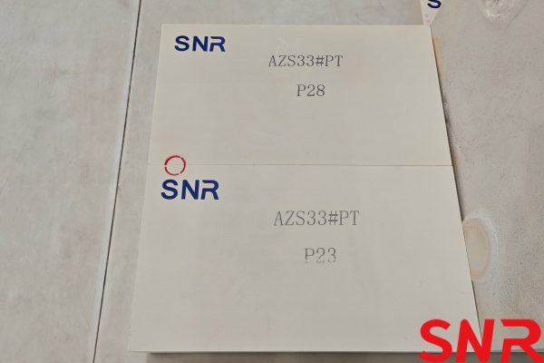
Regular Casting |
PT |
Shrinkage cavity at the center, uneven density |
Non-critical areas, e.g., regenerator walls, flues |
|
Tilt Casting |
QX |
Shrinkage cavity at one end, dense end facing service side |
Sidewall bricks, breastwall bricks |
|
Void-Free Casting |
WS |
Shrinkage cavity removed, fully dense brick |
Throat, electrode blocks, forehearth, gate |
|
End Casting |
ZWS |
Special process, no shrinkage cavity, uniform glass phase distribution |
High-end applications, e.g., optical glass furnaces |
Core principle: High-grade materials must be paired with high-grade casting methods. Using PT-grade AZS 41# blocks in the throat, where internal shrinkage cavities become erosion pathways, may yield performance inferior to WS-grade AZS 36# blocks.
5.2 Glass Phase Exudation and Foaming Control
Exudation characteristics of AZS 33#block: In the 1100–1200 °C range (e.g., regenerator top), exudation of the glass phase from AZS 33#block may form low-viscosity droplets that bond with dust, creating “hangings.” However, in the melting zone, the exudate is usually assimilated by the glass melt, with minimal impact.
“Hot-face spalling” mechanism of AZS 41#block: If AZS 41#block have high residual stress from annealing, the surface glass phase may exude at high temperatures, forming a dense layer. During temperature fluctuations, the difference in thermal expansion between this dense layer (enriched with ZrO₂, higher expansion) and the substrate can cause flake-like spalling, creating “zirconia-corundum” stones. Therefore, when using AZS 41#block, it is essential to ensure high-quality annealing and choose reputable manufacturers.
Foaming control: Glass phase exudation from AZS blocks into the glass melt can reduce surface tension and promote bubble formation. For high-quality glasses (e.g., optical glass, electronic glass), exudation must be strictly controlled, sometimes requiring surface treatments.
5.3 Jointing Mortar Compatibility
Different grades of AZS blocks must be laid with matching AZS ramming masses or mortars. Using ordinary high-alumina mortar with AZS 41#block is strictly prohibited due to:
→Chemical mismatch: high-alumina mortar and AZS 41#block have different thermal expansion coefficients, inducing stress at high temperatures.
→Corrosion resistance disparity: high-alumina mortar is readily attacked by alkali vapor, leading to joint cracking.
→Electrochemical corrosion: contact between dissimilar materials may create local galvanic effects, accelerating erosion.
Recommended practice:
Between AZS 41#block: use 41#-composition AZS mortar.
Between AZS 36# blocks: use36# -composition AZS mortar or compatible high-zirconia mortar.
At transitions between different grades: use mortar matching the higher grade to ensure reliability at the weakest points.
5.4 Expansion Joint Placement and Management
AZS blocks have a coefficient of thermal expansion around 6.5–7.5 × 10⁻⁶/°C, leading to significant volume increase during heat-up. Improper expansion joints can cause brick crushing or cracking.
AZS 33#block: higher glass phase content, more gradual expansion, expansion joints can be relatively small.
AZS 41#block: higher baddeleyite content, more concentrated expansion, ample expansion joints must be reserved.
Critical zones (throat, corners): require precise expansion joint design, sometimes using compensation materials.
5.5 Heating-up and Temperature Ramp Schedule
Due to poor thermal shock resistance of AZS blocks, heating-up rates must be strictly controlled:
Room temperature to 600 °C: ramp rate ≤ 15 °C/h, mainly removing free water.
600 °C to 1000 °C: ramp rate ≤ 20 °C/h, glass phase begins to soften.
Above 1000 °C: ramp rate may be increased, but glass furnace expansion must be monitored.
Soaking time: typically 14–21 days depending on glass furnace size.
For AZS 41#block in particular, too rapid heating can easily cause cracking. Some advanced glass furnaces adopt a “step-heating + soaking” precise control schedule.
6. Conclusion
AZS 33#block, AZS 36#block, and AZS 41#block are not in a simple “good versus bad” linear relationship; they are “special forces” designed for different battlefields and operating conditions:
AZS 33#block is a cost-effective “all-rounder”: suitable for zones with large temperature gradients and relatively mild corrosion, such as bottom paving, regenerators, flues, and doghouses. Its excellent thermal shock resistance and lower cost make it the first choice for non-critical areas.
AZS 36#block is a balanced “backbone” material: suitable for main structures subject to moderate loads, such as main sidewall sections, bottom corners, and breastwalls at hot spots. It achieves an optimal balance between cost and performance and serves as the main material for large glass furnaces.
AZS 41#block is a “special force” against tough enemies: must be used in the most critical bottlenecks, such as the glass line, throat, around electrodes, and forehearth gates. Its superior corrosion resistance provides the core guarantee for glass furnace longevity.
A scientific differentiated application strategy should follow these principles:
Use the best material (AZS 41#block) in the weakest zones: glass line, throat, around electrodes, forehearth gates.
Use moderate materials (AZS 36#block) in controlled main zones: main sidewall sections, bottom corners, breastwalls at hot spots.
Use economical materials (AZS 33#block) in non-critical zones: bottom paving, regenerators, flues, doghouses.
Match casting method with grade: high grades require high-grade casting methods.
Match jointing materials: use mortars consistent with brick composition.
Coordinate cooling and heating-up schedules: develop rational ramp-up and cooling plans based on material characteristics.
Only by doing so can glass furnace life be maximized, total construction and operating costs minimized, and glass quality ensured, achieving the greatest economic benefits in glass melting. With continuous advances in simulation technology, composite materials, and intelligent monitoring, the differentiated application of AZS blocks will become more refined and scientific, providing solid support for the high-quality development of the glass industry.
 I am Zoe. If you have any purchasing plans for fused cast AZS refractory blocks, please contact me.
zoe@snrefractory.com/ WhatsApp:+86 15670323812
 info@snr-azs.com
 +86-18203976036