

As the glass industry advances toward ultra-clear glass production and electric boosting technologies, the operating conditions of glass melting furnaces have become increasingly severe. Fused cast AZS (Alumina-Zirconia-Silica) blocks, as the core refractory material of glass furnaces, have their internal quality directly determine furnace service life and glass product quality. This article systematically introduces three non-destructive testing (NDT) techniques for fused cast AZS blocks—color measurement, radar-based cavity fill detection, and optical surface analysis—and deeply elaborates on the intrinsic relationships between each testing indicator and material service performance. Research shows that through precise control and inspection of block oxidation state, cavity distribution, and surface microstructure, glass bubble defects can be effectively reduced, glass phase exudation suppressed, and corrosion progression delayed, thereby significantly extending furnace life and improving glass quality. This article also provides detailed explanations of the spectrophotometer principle of color measurement, the mathematical definition and engineering application of the L*a*b* color space, and the methods for establishing acceptance standards based on exudation and bubble test results, offering actionable quality control guidelines for glass manufacturers and refractory suppliers.
1. Introduction: Challenges Facing Glass Furnaces and the Importance of Refractory Quality
2. Characteristics and Internal Defects of Fused Cast AZS blocks
3. Color Measurement: Determining Oxidation State from Color
4. Radar-Based Cavity Fill Detection: Cavity Localization and Fill Optimization
5. Optical Surface Analysis: Corrosion Control at Joints
6. Engineering Value of Non-Destructive Testing Technology
1. Introduction: Challenges Facing Glass Furnaces and the Importance of Refractory Quality
1.1 Industry Transformation and Escalating Operating Conditions
In recent years, the glass industry has been undergoing profound transformation. Two major trends are reshaping the design and operation of glass melting furnaces:
First, the "ultra-clear" trend in glass products. Market demand for high-transparency glass is growing daily. Whether for photovoltaic glass, high-end containers, or electronic glass, lower iron content and higher light transmittance are required. Ultra-clear glass production requires melting at higher temperatures, and the melting process causes more severe corrosion of refractories. This is because the viscosity characteristics of ultra-clear glass differ from ordinary soda-lime glass, requiring higher heat input and longer residence time for melting and fining.
Second, the "electrification" of furnaces. To reduce carbon emissions, more glass manufacturers are adopting electric boosting or all-electric melting furnaces. Electric boosting systems heat directly through electrodes immersed in the glass melt, altering the temperature distribution and glass flow patterns within the furnace. This change exacerbates corrosion of sidewall blocks, particularly at the bottom, because local temperatures around electrodes are higher and convective glass flow is stronger.
These two trends together make the operating conditions of glass furnaces unprecedentedly severe. Research shows that for every 50°C increase in temperature, the corrosion rate of refractories doubles. At the same time, furnace design life is continuously extending—from the traditional 3-5 years toward 8-10 years. Against this background, quality control of refractories is no longer just a routine inspection step in the procurement process but a core element affecting furnace safety and return on investment.
1.2 The Cost of Refractory Quality Problems
A single unqualified AZS block can bring catastrophic consequences to a glass manufacturer. From minor bubble defects causing product downgrading, to severe glass phase exudation contaminating the entire furnace batch, to extreme block cracking leading to glass leakage—each failure mode means enormous economic loss.
Taking a 500 ton per day float glass furnace as an example:
Product downgrading due to bubble defects can cost tens of thousands of RMB per day
An unplanned furnace shutdown caused by refractory quality issues can result in direct economic losses of tens of millions of RMB
Early cold repair to replace sidewall blocks requires not only millions of RMB in refractory material costs but also weeks of production loss
Therefore, ensuring that every AZS block entering the furnace has sufficiently high quality is an important part of glass manufacturer risk management. So how can this be achieved? The answer lies in the application of non-destructive testing technology.

1.3 The Value of Non-Destructive Testing
Non-Destructive Testing (NDT) refers to a class of technical methods that evaluate the internal and surface quality of an object without destroying it. For fused cast AZS blocks, the core value of NDT is reflected in three aspects:
First, achieving 100% full inspection. Traditional destructive testing can only sample a small number of specimens and cannot cover every block. NDT allows comprehensive screening of every block before shipment.
Second, early detection of hidden defects. Internal defects such as cavities and abnormal oxidation-reduction states cannot be seen with the naked eye and must be detected using specialized equipment before shipment.
Third, guiding process improvement. Accumulated NDT data can provide feedback to the production process, helping manufacturers continuously optimize process parameters.
This article will elaborate on three key NDT methods—color measurement, radar-based cavity fill detection, and optical surface analysis—and deeply explore the intrinsic relationships between each testing indicator and furnace service performance.
2. Characteristics and Internal Defects of Fused Cast AZS blocks
2.1 Basic Composition and Manufacturing Process
Fused cast AZS blocks are produced by melting a mixture of alumina (Al₂O₃), zirconia (ZrO₂), and silica (SiO₂) in an electric arc furnace at temperatures exceeding 2000°C, then casting the molten material into molds. The manufacturing process includes the following key steps:
Raw material batching: Accurately weigh the proportions of Al₂O₃, ZrO₂, and SiO₂ according to the target grade (33#, 36#, or 41#). ZrO₂ is the most expensive component, and its content directly determines the corrosion resistance of the product.
Electric arc melting: Melt the mixed raw materials in an electric arc furnace at 2000-2200°C. The electric arc furnace generates high temperatures through discharge between graphite electrodes. The furnace atmosphere can be controlled by adjusting ventilation and the amount of reducing agent.
Casting: Pour the molten material into pre-prepared sand or metal molds. Casting speed and mold design affect the temperature distribution during solidification, thereby affecting the location and size of cavities.
Annealing and cooling: The cast blocks undergo slow cooling in an annealing box over several days to weeks to eliminate internal stresses and prevent cracking.
Finishing: After cooling, the blocks undergo cutting, grinding, and other finishing processes to achieve specified dimensional accuracy and surface smoothness.
2.2 Microstructural Composition
The microstructure of fused cast AZS blocks consists of three main crystalline phases and a glass phase filling the spaces between crystals:
Corundum (α-Al₂O₃): Present as plate-like or columnar crystals, providing mechanical strength and a corrosion-resistant骨架. Corundum content accounts for approximately 40-50% of the total volume.
Baddeleyite (ZrO₂): Present as granular or dendritic crystals, this is the most corrosion-resistant component of the material. ZrO₂ undergoes a monoclinic-to-tetragonal phase transformation at approximately 1200°C, accompanied by a volume change of about 4%. This characteristic both gives the material some thermal shock resistance and serves as a driving force for glass phase exudation.
Glass phase (silicate matrix): An amorphous substance filling the spaces between crystals, primarily composed of SiO₂ with impurities such as Al₂O₃, Na₂O, and Fe₂O₃. The softening point of the glass phase is typically between 1100°C and 1200°C, making it the weakest link in the material.
Commercial grades are classified by zirconia content: AZS-33 (33% ZrO₂), AZS-36 (36% ZrO₂), and AZS-41 (41% ZrO₂). Higher zirconia content correlates with improved corrosion resistance but also increases manufacturing difficulty and cost.
2.3 Types and Causes of Internal Defects
Various internal defects can occur during the production of fused cast AZS blocks, primarily including:
Cavities: This is the most common and most harmful defect. Because the density of molten AZS material is lower than that of solid AZS (density difference approximately 0.2-0.3 g/cm³), volume shrinkage occurs during solidification after casting. The shrinkage concentrates in the last region to solidify, forming a cavity. Depending on the casting process, the location and size of cavities vary significantly: for conventional casting (PT/RT), cavities are concentrated in the upper part of the block, forming larger voids; for void-free casting (WS), special processes (such as insulated risers, vibration casting, etc.) completely remove or compress cavities to acceptable levels.
Microporosity: Gases in the melt (mainly from raw material decomposition and electric arc furnace atmosphere) that do not completely escape can form microporosity within the block. These pores are typically sub-millimeter in diameter and are potential pathways for glass penetration.
Glass phase segregation: Thermal gradients during casting and cooling can cause the glass phase to enrich in certain regions of the block. Glass phase-enriched regions have poorer corrosion resistance and can become starting points for localized failure.
Microcracks: Improper cooling rate control or insufficient annealing can generate thermal stress cracks within the block. These cracks can propagate during furnace operation, leading to block cracking.
Abnormal oxidation-reduction state: Improper atmosphere control during melting can result in the block being in a reduced state. Reduced-state blocks contain Fe²⁺, Fe⁰, or even residual carbon, which are harmful to glass quality.
These internal defects pose serious safety hazards for furnace operation. Traditional destructive testing (such as cutting and sampling) can only sample a small number of specimens and cannot cover every block. The value of NDT technology lies precisely in its ability to comprehensively screen every block without destroying it.
3. Color Measurement: Determining Oxidation State from Color
3.1 Mechanism Relating Color to Oxidation State
3.1.1 Spectral Characteristics of Variable-Valence Ions
The glass phase of fused cast AZS blocks contains small amounts of impurity ions, primarily iron and titanium ions, at concentrations on the order of tens of ppm. These ions have variable valence characteristics, and their form directly reflects the oxidation-reduction state of the block.
In the visible light spectrum, iron ions of different valence states have different absorption characteristics. Fe³⁺ (trivalent iron) has multiple absorption bands in the visible region, primarily absorbing blue-violet light, thus appearing in complementary colors—yellow to red. The exact hue depends on the coordination environment of Fe³⁺: tetrahedrally coordinated Fe³⁺ appears more yellow, while octahedrally coordinated Fe³⁺ appears more red. Fe²⁺ (divalent iron) has strong absorption in the near-infrared region and relatively weak, uniform absorption in the visible region, thus appearing light green to gray with lower color saturation.
When the block is in a fully oxidized state, iron exists as Fe³⁺, and the block appears light red or flesh-colored. When oxidation is insufficient, iron exists as Fe²⁺ or even metallic iron (Fe⁰), and the block appears gray-black. This relationship has been verified by X-ray absorption near-edge structure (XANES) spectroscopy.
3.1.2 Relationship Between Color and Bubble Defects
During glass production, bubbles are a common defect affecting quality. When molten glass contacts reduced-state (gray) AZS blocks, the following chemical reaction is triggered:
FeO/Fe⁰ + SO₄²⁻ → Fe₂O₃ + SO₂↑
The resulting sulfur dioxide bubbles are continuously released. The driving force for this reaction comes from the strong thermodynamic tendency of Fe²⁺/Fe⁰ to convert to Fe³⁺. Experimental studies using video-recorded bubble tests (soda-lime glass at 1350°C) show that fully oxidized AZS-36 blocks (L*=89.3, C*=6.1) have a transient bubble duration of only 8 hours, while gray AZS-36 blocks (L*=83.2, C*=8.0) have a bubble duration of up to 24 hours. Moreover, gray blocks produce larger and more dense bubbles.
More critically, as the furnace operates and the hot face gradually moves inward, the oxidation-reduction reactions within the block are repeatedly triggered, continuously generating new bubbles. Therefore, selecting fully oxidized blocks is a prerequisite for ensuring glass quality.
3.1.3 Relationship Between Color and Glass Phase Exudation
Glass phase exudation refers to the phenomenon where the glass phase within the block softens, liquefies at high temperatures, and exudes from the block surface. This is driven by two forces acting together:
First, phase transformation shrinkage of the zirconia skeleton. Zirconia undergoes a monoclinic-to-tetragonal phase transformation at approximately 1200°C, accompanied by a volume shrinkage of about 4%. This shrinkage compresses the glass phase filling the spaces between crystals, pushing it toward the surface.
Second, pressure from dissolved gases. Reduced-state blocks dissolve more gas (such as carbon monoxide, sulfur dioxide, hydrogen, etc.) during melting. The solubility of these gases in the glass phase decreases with increasing temperature. As the block heats up, gas exsolution generates additional pressure, further pushing the glass phase outward. The deeper the reduction, the greater the amount of dissolved gas and the stronger the exudation driving force.
Experimental data show that gray blocks have exudation rates 2-4 times higher than fully oxidized blocks. Glass phase exudation brings three hazards: first, exudation increases porosity within the block, reducing structural strength and accelerating corrosion; second, exuded glass can contaminate glass products, forming streaks, stones, or secondary zirconia crystallization defects; third, continuous exudation can cause dimensional changes in the block, affecting furnace structural stability.
3.2 Standardized Methods for Color Measurement
3.2.1 Why Instrumental Measurement Is Necessary
Because human color perception is affected by lighting conditions and individual observer differences, the same block may appear different colors under different lighting conditions, and different people may give different judgments. Therefore, standardized instrumental measurement methods must be used.
Human color perception is a complex physiological and psychological process. The human retina has three types of cone cells, sensitive to long-wave (red), medium-wave (green), and short-wave (blue) light respectively. The brain integrates the response signals from the three cell types to form color perception. However, the spectral responses of cone cells vary among individuals, and the spectral distribution of the illumination source also affects perception results.
Instrumental measurement eliminates these subjective factors, providing objective, quantifiable measurement results.
3.2.2 Measurement Principle of the Spectrophotometer
Currently, the industry uses spectrophotometers for reflectance measurement. The core components of a spectrophotometer include:
Light source: Typically a standardized D65 light source, simulating the average spectral distribution of daylight. After passing through a filter or monochromator, the light from the source forms monochromatic light of specific wavelengths or full-spectrum white light.
Integrating sphere: A spherical cavity with a highly reflective white coating on its inner wall. Light reflected from the sample surface is collected by the integrating sphere and homogenized through multiple diffuse reflections, eliminating directional effects.
Photodetectors: Three sensors simulating the spectral sensitivities of human cone cells, each equipped with filters matching the CIE standard observer functions. These three sensors measure the signal intensities of the red, green, and blue channels respectively.
Measurement process: A standardized flash lamp illuminates the sample surface. The integrating sphere collects the reflected light, and the sensors measure the reflected light intensity. The measurement results are compared with the reflectance of a standard white plate to calculate the reflectance spectrum of the sample. The reflectance spectrum is then converted to color coordinates according to the CIE standard colorimetric system.
3.2.3 Mathematical Definition of the L*a*b* Color Space
Measurement results are expressed in the CIE L*a*b* color space. This color space was defined by the International Commission on Illumination (CIE) in 1976 to provide a uniform color space consistent with human visual perception.
The three coordinates of the L*a*b* color space are defined as follows:
L (lightness):* Indicates the brightness or darkness of a color. L* = 0 corresponds to absolute black, and L* = 100 corresponds to an ideal diffuse white surface. The formula for calculating L* is based on the nonlinear perception of brightness by the human eye and is roughly proportional to the cube root of reflectance.
*a* (red-green axis):* Positive values indicate a reddish color, and negative values indicate a greenish color. a* = 0 indicates neutral gray. The absolute value of a* indicates the intensity of red or green tendency.
*b* (yellow-blue axis):* Positive values indicate a yellowish color, and negative values indicate a bluish color. b* = 0 indicates neutral gray.
Chroma C: Defined as the distance of the sample color from the gray axis in the ab* plane, calculated as C* = √(a² + b²). C* indicates color saturation or vividness—the larger the C* value, the more vivid the color; C* = 0 corresponds to completely achromatic gray.
Hue angle h°: Defined as arctan(b*/a*), indicating the position of the color on the color wheel. 0° corresponds to red, 90° to yellow, 180° to green, and 270° to blue.
For AZS blocks, fully oxidized (Fe³⁺-dominant) samples are positioned in the upper-right quadrant of the a*b* plane (positive a, positive b), appearing reddish-yellow. Reduced-state (Fe²⁺-dominant) samples are positioned near the origin (a* and b* both near zero), appearing gray.
3.2.4 Acceptance Standards Based on Colorimetric Values
Based on exudation and bubble test results, the industry has established acceptance standards based on colorimetric values. These standards apply to all parts where color measurement can be performed on clean saw-cut surfaces, including sidewall blocks, throat blocks, and submerged sidewall blocks.
Typical acceptance indicators are as follows:

It should be noted that the baseline colorimetric values may vary slightly between different grades (33#, 36#, 41#) because changes in ZrO₂ content and glass phase composition affect color appearance. Therefore, suppliers and users should establish reference databases for specific products.
3.2.5 Precautions for Measurement Operations
To ensure accuracy and repeatability of measurement results, the following precautions should be observed:
Sample preparation: The measurement surface should be a clean saw-cut surface, free of oil and dust. Surface roughness affects reflectance to some extent, so the finishing state should be consistent.
Measurement location: Multiple representative locations on the block should be measured, and the results averaged. Avoid single-point measurements at edges, cracks, or areas with obvious color differences.
Instrument calibration: Calibrate the instrument with a standard white plate before each measurement to ensure accuracy.
Environmental conditions: Avoid interference from strong ambient light; measurements should preferably be performed in a darkroom or under shaded conditions.
Data recording: Record the L, a, and b* values for each measurement, along with the measurement date, operator, block number, and other information for traceability.
4. Radar-Based Cavity Fill Detection: Cavity Localization and Fill Optimization
4.1 Formation Mechanism and Hazards of Cavities
4.1.1 Physical Nature of Solidification Shrinkage
The density difference between liquid and solid AZS material is the root cause for cavity formation. For AZS-33 material, liquid density is approximately 2.8-2.9 g/cm³ (above 2000°C), while solid density is approximately 3.7-3.8 g/cm³ (room temperature). The density difference is about 0.8-1.0 g/cm³, corresponding to a volume shrinkage of approximately 20-25%.
When the molten material is cast into a mold, cooling begins from the mold walls. The outer layer solidifies first, forming a hard shell, while the interior remains liquid. As temperature further decreases, the interior liquid material undergoes volume shrinkage upon solidification, but because the outer layer has already solidified, material cannot be supplied from outside, so a cavity forms in the last region to solidify.
4.1.2 Cavity Characteristics of Different Casting Processes
Depending on the casting process, the location and size of cavities vary significantly:
PT grade (regular cast): Cavities are concentrated in the upper part of the block, forming larger voids in specific areas. Cavity volume accounts for 5-15% of the total block volume. This type of block is suitable for non-critical areas, such as upper sidewalls and breast walls.
ZWS grade (near-void-free): Through optimized casting processes (such as controlling casting speed, using insulated risers, adjusting mold design, etc.), cavities are compressed to minimal residual. Cavity volume is typically less than 3%. This type of block is suitable for general sidewalls and moderately corrosive areas.
WS grade (void-free): Using special processes (such as vibration casting, pressure casting, or riser removal), cavities are completely eliminated. The block is dense and uniform, with no visible voids. This type of block is suitable for the most severe areas, such as throats, tuckstones, around electrodes, and near the glass line.
4.1.3 Effect of Cavities on Corrosion Rate
Cavity areas are "superhighways" for glass penetration. Once molten glass enters a cavity area, the local corrosion mechanism fundamentally changes:
In dense block, corrosion is a slow diffusion-controlled process. Alkali ions from the glass diffuse through the block‘s pore network, reacting with block components to form a reaction layer. The thickening of the reaction layer slows further diffusion.
In cavity areas, molten glass directly enters the void, contacting fresh internal block surfaces. This is a convective mass transfer process, with rates orders of magnitude faster than diffusion. Simulation studies show that local corrosion rates in cavity areas can be more than 4 times higher than in dense areas.
If a cavity is exposed during furnace operation, it can lead to accelerated corrosion or even glass leakage, with catastrophic consequences.
4.2 Principles and Methods of Radar-Based Detection
4.2.1 Basic Principles of Ground Penetrating Radar
Ground Penetrating Radar (GPR) technology is applied to fill detection of AZS blocks. Its principle is similar to that of military radar and geological exploration radar.
The radar system includes three core components:
Transmitting antenna: Emits electromagnetic pulses of a specific frequency into the block. Frequencies typically range from 500 MHz to 2 GHz. Higher frequencies provide higher resolution but lower penetration depth.
Receiving antenna: Receives electromagnetic wave signals reflected from internal interfaces within the block.
Control and processing unit: Controls the timing of transmission and reception, amplifies, filters, and analog-to-digital converts the received signals, and generates visual images.
When electromagnetic waves propagate through the block, reflections occur at interfaces where the dielectric constant changes. The interface between refractory (dielectric constant approximately 6-10) and air (dielectric constant = 1) produces the strongest reflection. Therefore, cavities (voids filled with air) generate strong reflection signals.
4.2.2 Detection Process and Data Processing
The radar detection procedure is as follows:
Preparation: Place the block on a detection table and clean the surface. For large blocks, multiple scans may be needed and the images stitched together.
Parameter setting: Select appropriate center frequency and time window based on block dimensions and expected defect sizes. For typical AZS blocks (200-400mm thickness), a 1 GHz antenna provides sufficient penetration depth and resolution.
Scanning: Perform linear scans along the length of the block, or grid scans to cover the entire block. Scanning speed should be uniform to avoid jitter.
Data processing: Raw radar signals undergo background removal, gain adjustment, bandpass filtering, and other processing to generate B-scan images. B-scan images use time as the vertical axis (corresponding to depth) and scan position as the horizontal axis, with reflection signal intensity represented by color tones.
Defect identification: Trained professionals identify the location, size, and morphology of cavities based on reflection characteristics in the B-scan image. Cavities typically appear as high-amplitude hyperbolic reflection features.
4.2.3 Acceptance Standards Based on Radar Detection
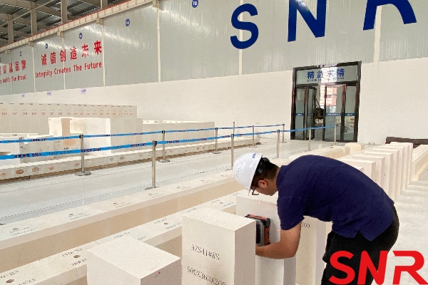
Currently, all critical-area sidewall blocks undergo radar scan acceptance before pre-assembly. Acceptance standards primarily include:
Cavity location: Cavities must be located in non-critical areas of the block, sufficiently far from the glass contact surface. For sidewall blocks, cavities should be in the upper part of the block and at a distance not less than a specified value (e.g., 50mm) from the top surface.
Cavity size: Maximum cavity dimensions must not exceed specified limits. For ZWS grade blocks, cavity diameter is typically required to be less than 10mm.
Fill ratio: The volume rate of dense material in the block. WS grade requires fill ratio ≥98%, ZWS grade requires ≥95%.
No cracks: The radar image should not show reflection features indicative of cracks.
4.3 Fill Requirements Under New Operating Conditions
The application of ultra-clear glass production and high-power electric boosting technologies significantly increases the temperature at the bottom of sidewall blocks. This changes the progression pattern of the corrosion front and raises higher fill requirements.
Traditional conditions: Corrosion of sidewall blocks primarily occurs near the glass line, with bottom corrosion relatively slow. Therefore, cavities located in the upper part of the block were considered safe.
New conditions: Under electric boosting, glass temperatures near electrodes are higher and convection is stronger. Corrosion rates at the bottom of sidewall blocks increase, and the corrosion front gradually moves upward. Research shows that for standard RR grade blocks, assuming the temperature profile of an ultra-clear glass float furnace and assuming a corrosion rate in cavity areas 4 times that of dense areas, cavities would be exposed after approximately 11 years.
Although this time seems long, the risk can become significantly earlier under conditions of higher electric boosting power, larger cavity sizes, or more aggressive glass compositions. Therefore, for high-power electric boosting or ultra-clear glass production lines, traditional RR grade blocks are no longer suitable. ZWS or even WS grade blocks with better fill characteristics must be selected to ensure cavities are away from the corrosion front.
5. Optical Surface Analysis: Corrosion Control at Joints
5.1 Special Characteristics of Joint Corrosion
The joints between fused cast AZS blocks are weak links in furnace construction. At the joints, several unfavorable factors exist:
Geometric discontinuity: Even with precision machining, micron-scale gaps remain between blocks. These gaps become initial pathways for glass penetration.
Stress concentration: Mismatch in thermal expansion at joints can generate local stresses, accelerating crack initiation and propagation.
Different chemical environment: Glass composition at joints may change due to local differences in diffusion and convection conditions.
Due to these factors, corrosion rates at joints are often higher than on the block bodies themselves. Therefore, joint quality control is an important part of ensuring overall furnace life.
5.2 Factors Affecting Surface Quality
During solidification of AZS blocks, different microstructures form on the surface versus the interior:
Surface layer (chill layer): Areas near the mold cool quickly, forming fine columnar crystal structures. Grain sizes are typically on the order of tens of micrometers, with orientations perpendicular to the mold wall. Due to rapid cooling, the glass phase is relatively uniformly distributed and porosity is low.
Transition layer: Between the surface layer and the core, grain sizes gradually increase, and columnar crystals transition to equiaxed crystals.
Core: Cooling is slow, thermal gradients are small, and coarse equiaxed crystal structures form. Grain sizes can reach the millimeter scale. Due to the cumulative effect of solidification shrinkage, the core may contain cavities and glass phase segregation.
This microstructural difference causes different corrosion behavior between the surface layer and the core. The fine columnar crystal structure, with more and more tortuous grain boundaries, generally has better resistance to penetration. Therefore, preserving an intact surface layer is beneficial for joint quality.
5.3 Optical Inspection Tools
Optical surface analysis uses several tools to assess block surface quality:
Optical microscope: Used to observe surface micro-morphology, evaluate grain size, glass phase distribution, and microcracks. Magnification typically ranges from 50-500x.
3D profilometer: Measures the three-dimensional surface topography and calculates roughness parameters (Ra, Rz, etc.). Roughness at joints affects sealing performance.
Machine vision system: Uses high-resolution cameras and image processing software to automatically identify macroscopic defects such as scratches, pits, and chips on the surface.
5.4 Joint Finishing Quality Requirements
Based on optical inspection results, the following requirements are placed on joint finishing quality:
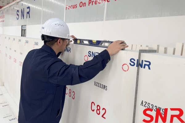
Flatness: The flatness error of the joint surface should be less than 0.1 mm per meter, ensuring tight fit between blocks.
Roughness: The surface roughness Ra of the joint surface should be less than 3.2 μm. Excessively high roughness leads to poor sealing.
No chipping: Joint edges should be intact, with no chipping, corner loss, or other defects.
Uniform glass phase distribution: The surface should not have obvious areas of glass phase enrichment or depletion.
6. Engineering Value of Non-Destructive Testing Technology
6.1 The Qualitative Change from "Sampling" to "Full Inspection"
Traditional destructive testing can only sample a small number of specimens, with the following limitations:
Insufficient representativeness: Due to batch-to-batch variability in AZS block quality, test results from a few specimens may not represent the entire batch.
Destructive nature: Tested specimens cannot be used, increasing cost.
Time-consuming: Specimen preparation (cutting, grinding, polishing) takes considerable time, making rapid release difficult.
The application of NDT technology enables 100% quality screening of every block before shipment. Taking radar detection as an example, all critical-area sidewall blocks undergo scan acceptance before delivery. This "zero-defect" quality philosophy provides solid assurance for safe furnace operation.
6.2 Extending Furnace Life
Through the integrated application of the three NDT techniques described above, the quality control level of fused cast AZS blocks has achieved a qualitative leap:
Oxidation control ensures exudation rates are reduced by 2-4 times, delaying block loosening and degradation, extending furnace life by 1-2 years
Fill optimization ensures cavities are away from the corrosion front, eliminating the risk of accelerated corrosion, extending life by an additional 1-1.5 years
Surface quality control ensures sealing at joints, reducing localized corrosion, contributing 0.5-1 year
Integrating these optimization measures, furnace service life can be extended from the traditional 3-5 years to 6-8 years.
6.3 Improving Glass Quality
Bubbles, streaks, and stones are important factors affecting glass product grade. Selecting fully oxidized blocks effectively suppresses bubble generation. Controlling glass phase exudation reduces streaks and crystallization defects. This is particularly important for producing high-end glass products such as pharmaceutical glass, electronic glass, and photovoltaic glass.
Taking ultra-clear photovoltaic glass as an example, bubble density is a key indicator determining light transmittance. Furnaces using fully oxidized blocks can reduce bubble defect rates by more than 50%, directly improving product yield and profit margins.
6.4 Supporting Low-Carbon Transformation
As the glass industry transitions toward low-carbon technologies such as electric boosting and all-electric melting, refractories face increasingly severe operating conditions. Only by ensuring material quality through rigorous NDT can the adoption of these new technologies be supported. In this sense, NDT technology is an important enabler for the glass industry to achieve carbon neutrality goals.
The internal quality of fused cast AZS refractories directly determines the service life of glass melting furnaces and the quality of glass products. This article has systematically introduced three NDT techniques for AZS blocks and their engineering significance:
Color measurement (spectrophotometry): Determines oxidation state by measuring L*a*b* colorimetric values. Fully oxidized blocks (L≥85, a≥2.0, C* 5-15) significantly reduce bubble defects and reduce glass phase exudation rates by 2-4 times.
Radar-based cavity fill detection: Uses ground penetrating radar to scan the interior of blocks, precisely locating cavity positions and sizes. WS/ZWS grade blocks ensure cavities are away from the corrosion front, eliminating the risk of accelerated corrosion.
Optical surface analysis: Inspects the microstructure of block surfaces and the quality of joints, ensuring corrosion resistance in critical areas.
Research shows that in the context of ultra-clear glass production and electric boosting technology adoption, traditional quality control standards are no longer sufficient to meet increasingly severe operating conditions. Only by adopting systematic NDT solutions and achieving the qualitative change from "sampling" to "full inspection" can long-term safe operation of furnaces be ensured.
Looking to the future, with developments in sensor technology, data processing, and artificial intelligence, NDT will evolve toward greater precision and intelligence. The establishment of automated inspection lines will allow each block‘s inspection data to be association with production batches and casting parameters, forming a complete quality traceability system. Big data analysis will help identify key process parameters affecting quality, promoting continuous optimization of refractory manufacturing processes.
For glass manufacturers, incorporating NDT requirements into refractory procurement specifications and establishing incoming inspection systems are effective means of controlling quality risk. "Penny-wise" approaches to refractories should focus not only on purchase price but also on total lifecycle cost. Selecting high-quality AZS blocks that have undergone rigorous NDT, though increasing initial investment, yields longer furnace life, more stable glass quality, and lower overall costs—an equation that every glass manufacturer should carefully consider.
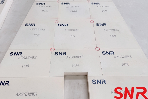
Henan SNR Refractory Co., Ltd. has been specializing in the production of fused cast AZS blocks for more than 25 years. We use high-quality raw materials and advanced fusion and casting technology and equipment to provide customers with high-quality products. From raw material procurement to finished product delivery, every step is strictly quality inspected to ensure that every indicator meets the standards, so you can use it with confidence.
Should you have any inquiries or specific requirements, our team is ready to provide professional support and tailored solutions.
 Contact Information:
Web: www.snr-azs.com
Email:[email protected]


 +86-18203976036