

Based on actual operating conditions, this paper discusses and analyzes the design and technical application of a large-scale oxy-fuel combustion photovoltaic glass furnace. From the overall layout to the melting zone, doghouse, bottom structure, breast wall structure, throat structure, and crown structure, design calculations are carried out. The configuration of refractory materials for key parts is explained, and design ideas and operational suggestions for large-scale oxy-fuel combustion photovoltaic glass furnaces are proposed.
Introduction
In the traditional air-assisted combustion technology used in the glass industry, oxygen is obtained from air, where oxygen accounts for only about 21%, while nitrogen (78%) does not participate in the combustion reaction and can react with oxygen at high temperatures to form nitrogen oxides (NOx), resulting in substantial heat loss and severe environmental pollution. Oxy-fuel combustion technology uses oxygen for combustion, eliminating the heating of non-participating nitrogen. It can reduce NOx emissions by more than 80%, lower investment and operating costs for flue gas treatment, and is of great significance for energy saving and achieving China‘s "carbon peak and carbon neutrality" strategic goals. Oxy-fuel combustion requires no reversing, has a stable flame and strong radiation capacity, increasing glass furnace thermal efficiency by over 15% and reducing unit product energy consumption by more than 25%. Compared with traditional air-assisted combustion, it offers significant advantages in energy conservation, environmental protection, product quality, construction and production costs, and subsequent maintenance. It has tremendous development potential and is particularly suitable for the production of high-transmittance, high-quality photovoltaic glass.
This paper does not elaborate on the theory and advantages of oxy-fuel technology over air-assisted combustion but focuses on discussing design and application technologies for large-scale oxy-fuel combustion photovoltaic glass furnaces with pull rates of 750–1000 t/d. Glass furnaces with pull rates of 800 t/d and 1000 t/d are used as examples for reference.
1. Overall Glass Furnace Layout
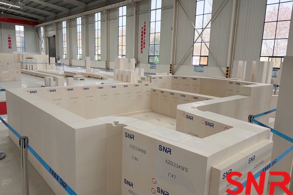
The biggest difference between large-scale oxy-fuel photovoltaic glass furnaces and air-combustion glass furnaces is the use of oxygen for combustion, eliminating the need for reversal, and consequently removing the port and regenerator settings. The design adopts a “one glass furnace, four lines” configuration with a cross-flame pattern. Oxy-fuel burners on both sides of the glass furnace fire continuously. Front and rear dual vertical flues are used for exhaust. Blanket-type batch chargers are applied, and the doghouse is sealed with a new type of oxy-fuel equal-width composite suspended wall. The bottom structure incorporates bubbling and multi-step stepped design. A throat water-cooled tube bank structure connects the melting zone to the crossover channel. An overflow system for the oxy-fuel glass furnace and a temperature/pressure regulation system for the channels are installed. The basic layout structure is similar for glass furnaces with pull rates of 750–1000 t/d.
2. Layout Design of the Melting Zone
2.1 Determination of Melting Rate
The melting rate of a glass furnace is related to many factors. There are various theoretical calculation methods both domestically and internationally. When the process control level, refractory selection, and glass furnace insulation are of high quality, a higher melting rate can be selected. Oxy-fuel photovoltaic glass furnaces have high flame emissivity and temperature, leading to improved heat utilization. The large amount of water vapor in the combustion products increases the OH⁻ concentration in the glass melt. The melting rate can be set about 15% higher than that of air glass furnaces. Based on actual production conditions, the melting rate for an 800 t/d oxy-fuel photovoltaic glass furnace is taken as 2.65 t/(m²·d), and for a 1000 t/d glass furnace as 2.75 t/(m²·d). A safety margin is retained; as large forming rolls are updated rapidly, production can be increased appropriately based on actual operation.
2.2 Glass Furnace Width Design
The crown of an oxy-fuel glass furnace is made of fused cast material, constructed with single rings dry-laid. Each individual crown block weighs over 300 kg, resulting in substantial total weight, demanding high standards for expansion and operation. For safety, the crown span should not be too large. Moreover, because both side burners fire simultaneously, there is no port suction opposite the flame, making the flame rigid and highly penetrating, shorter than in air glass furnaces. To prolong the residence time of high-temperature gases in the glass furnace, the length-to-width ratio of the oxy-fuel glass furnace is appropriately increased. Considering all factors, the glass furnace width is designed as 11,000 mm for 800 t/d and 12,000 mm for 1000 t/d.
2.3 Melting Zone Design
2.3.1 Melting Zone Area
Fm = G / K
Where: Fm = melting area (m²); G = production capacity (t/d); K = melting rate (t/(m²·d)).
① 800 t/d melting area = 800 / 2.65 = 301.9 m²;
② 1000 t/d melting area = 1000 / 2.75 = 363.6 m².
2.3.2 Melting Zone Length
Lm = Fm / Bm
Where: Lm = melting zone length (mm); Bm = melting zone width (mm).
① 800 t/d oxy-fuel glass furnace melting zone length = 301.9 / 11 = 27445 mm;
② 1000 t/d oxy-fuel glass furnace melting zone length = 363.6 / 12 = 30300 mm.
2.4 Burner Layout
2.4.1 Burner Arrangement
In oxy-fuel glass furnaces, burners on both sides fire simultaneously, producing a stable flame with high temperature and complete combustion, which benefits glass melting and output. The flame from an oxygen-fuel burner consists of visible and invisible parts; the invisible dark flame accounts for 30% to over 35% of the total. When opposed firing is used, the invisible parts of opposite flames may collide and rise toward the crown, accelerating crown erosion. Simply changing from opposed to staggered firing could cause uneven temperature distribution across the glass furnace width, affecting flow field stability and reducing melting quality. To address this, the first and last pairs of burners in the melting zone adopt opposed firing, while the remaining burners are arranged in a staggered pattern. This increases flame coverage and prevents the invisible dark flame parts from colliding and rising toward the crown. The burners in the first and last pairs that are placed on the same span as the adjacent burners use low-power burners to compensate for temperature non-uniformity caused by staggered firing. Reserved burner ports in the fining zone allow both opposed and staggered firing as process adjustments, increasing process flexibility.
2.4.2 Burner Layout Design
(1) Distance from the centerline of No.1 flue: In oxy-fuel glass furnaces, the flue outlet and each burner occupy an equal width. If the front No.1 flue is placed too close to the doghouse, it can damage the L-shaped suspended wall; if too far, the No.1 burner will be far from the batch pile, which is the area of highest heat absorption in the glass furnace, affecting melting. Thus, the distance from the centerline of No.1 flue to the front is designed as 2400 mm for 800 t/d and 2600 mm for 1000 t/d.
(2) Number of burner pairs: The glass furnace uses new high-power oxy-fuel burners. Based on flame coverage and ensuring combustion effectiveness without interference, the spacing for high-power burners is set at 2900 mm. To achieve the arrangement described above, the No.1 burner is placed 0.75 times the burner spacing from the No.1 flue centerline, and the low-power burners in the first and last pairs (placed on the same span as adjacent burners) occupy 0.5 times the burner spacing.
Calculation of burner pairs:
① 800 t/d oxy-fuel glass furnace: (27445 - 2400 - 1000 - 0.75×2900 - 0.5×2900) / 2900 ≈ 7
=> 8 pairs of high-power burners + 1 pair of low-power burners. Distance from No.1 burner to the pre-melting zone = 2400 + 0.75×2900 = 4575 mm.
Revised melting zone length: 2400 + 0.75×2900 + 7×2900 + 0.5×2900 + 1000 = 27325 mm, melting rate = 2.66.
② 1000 t/d oxy-fuel glass furnace: (30300 - 2600 - 1000 - 0.75×2900 - 0.5×2900) / 2900 ≈ 8
=> 9 pairs of high-power burners + 1 pair of low-power burners. Distance from No.1 burner to pre-melting zone = 2600 + 0.75×2900 = 4775 mm.
Revised melting zone length: 2600 + 0.75×2900 + 8×2900 + 0.5×2900 + 1000 = 30425 mm, melting rate = 2.74.
2.4.3 A triangular protruding section is designed above the burners to divert breast wall run-off and prevent vertical flow in front of the burner that could affect the flame shape.
2.5 Fining Zone Design
2.5.1 Definition
In an oxy-fuel photovoltaic glass furnace, the fining zone is defined as the area from 1 m behind the centerline of the last burner pair to the entrance of the throat. Its function is to provide sufficient residence time for the glass melt in the glass furnace, allowing the melt (initially qualified after melting) to fine and remove remaining bubbles. As pull rate increases, the flow velocity across the glass furnace cross-section rises, and the temperature drop per unit length along the glass furnace decreases; consequently, the ratio of fining zone area to melting zone area gradually increases. Due to the high thermal efficiency of oxy-fuel glass furnaces, differences exist in flow velocity, thickness, and viscosity of the upper current. Considering all factors, the ratio of fining zone area to melting zone area is set at 30% for 800 t/d and 32% for 1000 t/d.
2.5.2 Fining Zone Length and Area Calculation
Fc / (Fm + Fc) = ratio of fining area to melting area
Lc = Fc / Bm
Where: Fc = fining zone area (m²); Lc = fining zone length (mm).
① 800 t/d oxy-fuel glass furnace: fining zone length = 11762 mm → 11800 mm, area = 129.8 m².
② 1000 t/d oxy-fuel glass furnace: fining zone length = 14260 mm → 14300 mm, area = 171.6 m².
2.6 Melting Zone Total Length
① 800 t/d oxy-fuel glass furnace: 2400 + 0.75×2900 + 7.5×2900 + 1000 + 11800 = 39125 mm
② 1000 t/d oxy-fuel glass furnace: 2600 + 0.75×2900 + 8.5×2900 + 1000 + 14300 = 44725 mm
2.7 Melting Zone Structural Dimensions
See Table 1.
|
Table 1 Melting Zone Structural Dimensions |
||
|
Parameter |
800 t/d |
1000 t/d |
|
Melting rate / [t/(m²·d)] |
2.66 |
2.74 |
|
Pre-melting zone length / mm |
1800 |
1800 |
|
Distance from No.1 flue centerline to pre-melting zone / mm |
2400 |
2600 |
|
Melting zone length / mm |
27325 |
30425 |
|
Melting zone width / mm |
11000 |
12000 |
|
Melting zone area / m² |
300.575 |
365.1 |
|
Fining zone length / mm |
11800 |
14300 |
|
Fining zone area / m² |
129.8 |
171.6 |
|
Ratio of fining zone to melting zone / % |
30 |
32 |
|
Total melting zone length / mm |
39125 |
44725 |
|
Total melting zone area / m² |
430.375 |
536.7 |
3. Doghouse Design
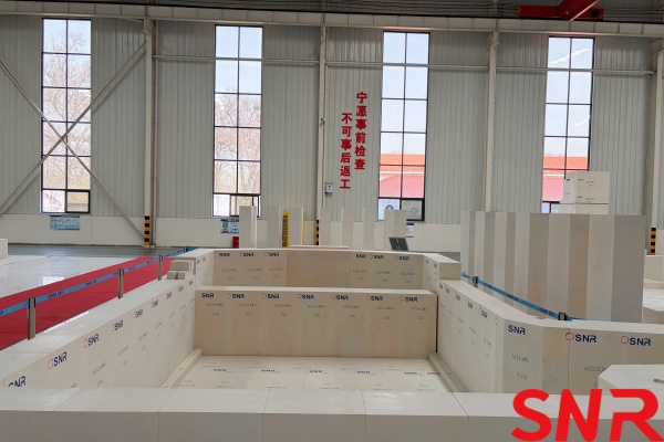
In oxy-fuel glass furnaces, the No.1 burner is relatively far from the front tank wall. Therefore, the pre-melting zone length is designed as 1800 mm. A blanket-type batch charger with thin-layer feeding is used. A new type of oxy-fuel large-nose-area, high-armored, flexible-force-adaptive suspended wall is designed to seal the doghouse. The suspended wall uses composite materials: the nose area uses zirconia-based sintered material to withstand thermal shock, while the part above the nose uses fused cast AZS block, allowing two glass furnace campaigns. This design can be referenced for air glass furnaces as well. The sidewall blocks on both sides of the pre-melting zone have a thickness of 300 mm, partially overlapping with the side tank walls, which narrows the doghouse width by 600 mm. While maintaining the same width for feeding, this reduces the erosion of the tank wall by the batch blanket.
4. Bottom Structure
(1) Glass furnace bottom structures are gradually evolving towards multiple steps. Especially for oxy-fuel photovoltaic glass furnaces, where the glass melt has low iron content, high transparency, and excellent heat transmission, designing a deeper tank depth at the front and gradually raising the bottom toward the middle and rear ensures a high melting rate and a certain glass withdrawal ratio. The front deep section prolongs the residence time of batch materials in the high-temperature zone, ensures glass melt convection, increases melt volume, facilitates batch melting, improves the melting rate, and protects bottom refractories. The rear fining zone adopts a shallow bottom design, reducing the glass flow layer thickness, relatively increasing the melt temperature in that area, shortening bubble removal time, and favoring homogenization and micro-bubble removal. It also limits backflow, achieving some energy savings.
(2) For large-scale oxy-fuel photovoltaic glass furnaces, the front tank depth is designed around 1500 mm, with about four steps gradually raising the bottom height to about 1000 mm. The number of steps should not be too few, and each step height should be controlled within 150 mm to reduce erosion and scouring. A step is also provided at the throat exit to effectively block bottom sediment.
(3) Various bottom configurations exist for photovoltaic glass characteristics in recent years: clay large blocks + sintered AZS + ramming mass + fused cast AZS block. The thickness of the two AZS layers should be appropriately increased.
(4) Bubblers are arranged at the hot spot of the glass melt, slightly behind the hot spot of the breast wall. The bubbling device effectively strengthens two longitudinal recirculation flows, enhancing melting. Bubbler spacing is around 600 mm, with bubble diameters tangent to each other, not too large. The distance from the sidewall is about 1000 mm to reduce sidewall erosion. Practice shows that the erosion of the paving blocks before and after the bubblers is no different from other areas, and no reinforcement is necessary.
(5) A weir (or sill) is a separation device in glass furnaces that effectively blocks glass melt backflow, stabilizes circulation loops, and stabilizes flow. Due to the "shallow layer effect," it enhances fining, maintains stable flow velocity and layer thickness within the glass furnace, and ensures melting quality even during large pull rate changes. The weir also prevents unmelted glass from the bottom of the melting tank from entering the fining zone, improving product quality. Large photovoltaic glass furnaces typically have four or more branch channels; frequent product changes cause large pull variations, affecting the flow field and especially bottom temperature fluctuations, impacting product quality. More branch channels mean more product changes and thus more quality disturbances. A weir can effectively solve this problem. However, the weir protrudes from the bottom, is immersed in glass on three sides, and erodes severely during operation. The high glass velocity above the weir and vortex formation at the joint with the sidewall block accelerate erosion. Stones generated from erosion can seriously impact product quality, limiting weir application mainly to small and medium glass furnaces, or omitting it entirely. By redesigning the weir block shape, adding weir corner protection blocks, and implementing dual water and air cooling, weir service life is greatly extended, vortices at the corners are eliminated, and erosion is mitigated. The weir size can be increased, making it applicable to medium and large glass furnaces, benefitting glass output and quality. The weir water box is designed as a plug-in, wheel-type structure that is simple and easy to replace. Given the high melting rate and small withdrawal ratio of oxy-fuel photovoltaic glass furnaces, installing a weir can prolong melt residence time in the melting zone, improving melting. Verification in several large photovoltaic glass furnaces shows that weir erosion has been solved, and there are no circulation conflicts. However, debate continues on whether to install a weir, as both options have pros and cons. Steps and bubblers can basically meet production needs; a weir provides additional stabilization, but the energy cost (air and water cooling) can reach several million yuan over a campaign, so cost must be considered.
5. Breast Wall Structure
5.1 Inner Width of Breast Wall
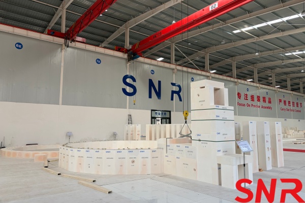
To minimize the crown span of oxy-fuel glass furnaces, the inner width of the breast wall should be reduced as much as possible. To protect the breast wall support plates and reserve space for patching blocks, each side breast wall usually extends outward by 300 mm. If this width is too small, after erosion of the 250 mm thick tank wall block, there will be insufficient space for patching, and the breast wall support plate may become exposed to the flame space. To provide room for two patching operations, the hook block head would have to be made longer, risking fracture. If too large, the crown span increases. Considering all factors, a 300 mm outward extension on each side remains.
5.2 Breast Wall Height
Breast wall height is related to the volumetric heat load of the flame space (melting zone chamber heat load), referring to the heat released by fuel combustion per unit flame space volume per hour. Combined with the heat load on the glass melt surface in the melting zone, it reflects the heat-receiving capacity of the melting zone structure and the glass furnace’s melting capacity. Once the melting zone area is determined, the factor affecting the chamber heat load is the flame space height. The crown angle range is relatively small and easy to determine; after the crown rise is fixed, the breast wall height determines the flame space volume. The flame space must have a certain volume to allow complete fuel combustion and full heat release. This value depends on pull rate, product, glass furnace type, tank depth, etc. To maximize radiative heat transfer from the crown to the glass melt, the flame space height should be appropriately reduced while ensuring a certain gas layer thickness and combustion space. Too large a value increases heat loss and specific energy consumption. Too small a volume prevents complete combustion and accelerates crown wear. For oxy-fuel glass furnaces with fused cast crowns, the horizontal thrust (plus the crown’s weight) puts considerable stress on the crown structure. The single-ring construction of the oxy-fuel crown requires special attention to safety. All things considered, the breast wall height of oxy-fuel glass furnaces can be reduced by about 10% compared to air glass furnaces; large oxy-fuel photovoltaic glass furnaces should maintain a height above 1500 mm. For 800 t/d and 1000 t/d glass furnaces, a breast wall height of 1600 mm is selected.
5.3 Flue Design
One pair of flues is installed at the front and rear of the combustion zone to exhaust combustion gases. Horizontal flue passages (similar to ports) connect to vertical flues leading to the main flue on the ground floor. The vertical flue structure resembles a regenerator. Since both sides fire simultaneously in oxy-fuel glass furnaces, there is no flue opposite the middle burners. If flues were placed in the middle of the combustion zone, they would reduce burner placement and allow high-temperature flue gases to escape directly. Therefore, flues are located only at the front and rear of the combustion zone, prolonging the residence time of hot gases and increasing melting efficiency. In air glass furnaces, the first few ports have higher gas volumes; dampers at the middle and rear are raised higher than those at the front to retain heat longer in the glass furnace. For oxy-fuel glass furnaces, front and rear damper settings differ; raising the rear damper significantly raises the temperature at the rear of the melting zone but lowers the BW temperature (forming zone temperature), which may increase specific energy consumption to maintain forming temperature. Hence, the inlet sections of the front and rear horizontal flues are kept the same. Dilution air holes are reserved in the upper part of the vertical flues, and louver dampers on the first floor adjust flue temperature. However, this measure is rarely used to reduce NOx emissions.
6. Throat Structure
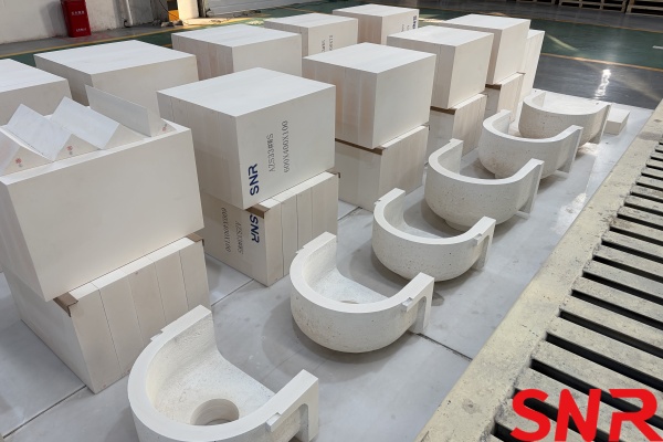
Current throat designs are trending shorter and narrower. Photovoltaic glass products are increasingly thin (2.0 mm, 1.6 mm), requiring higher glass temperatures. Stirrer positions previously reserved are rarely used by manufacturers, so throat length is being shortened. To reduce backflow in the cooling zone and save energy, throat width is also narrowing. However, severe refractory erosion occurs at the narrowed throat, especially at the corner blocks at the liquid level. This area is narrow and obstructed, making hot repair difficult and becoming a weak point in photovoltaic glass furnaces. Despite the trend toward shorter and narrower throats, a certain width must be preserved. The glass velocity in the throat should be controlled at 4–5 m/h (higher value for higher pull rates). For this design, throat width is 2800 mm for 800 t/d and 3000 mm for 1000 t/d. At the throat entry corner blocks, water-cooled wrap tubes and vertical air nozzles are installed, along with independent air nozzles at the liquid level. In the later glass furnace campaign, erosion may create a groove where the throat water cooler contacts the sidewall liquid level; a small water cooler is pre-installed to prevent erosion.
7. Crown Structure
Crown design is critical for oxy-fuel glass furnaces. The exhaust gases from oxy-fuel combustion are mainly CO₂ and H₂O, with water vapor content 3.5 times that of air glass furnaces. The flue gas volume is only 30% of that of air glass furnaces, and the alkali vapor concentration rises significantly. Therefore, fused cast materials resistant to alkali attack must be used. The crown accounts for over 40% of the total weight of fused cast materials and over 30% of the total refractory cost. It also presents high safety risks. The crown surface accounts for over 70% of the total flame space surface area and is a key area for controlling heat loss. Thus, proper crown structure, material, and insulation must be selected to improve safety and economy, enabling two campaigns for the fused cast crown.
7.1 Crown Material Configuration
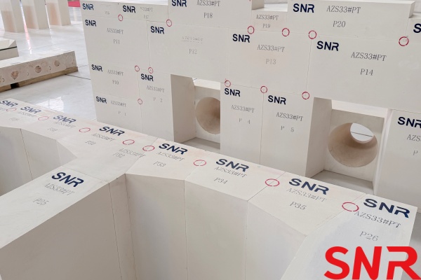
Currently, fused cast AZS block and fused cast α-β alumina blocks are mainly used. Fused cast AZS block is less expensive than α-β alumina, has good resistance to temperature fluctuations at high temperatures and batch dust, but exudes a glassy phase above 1400 °C. α-β alumina has excellent resistance to Na₂O vapor corrosion, contains almost no glassy phase, is very pure, but is more expensive. Combining their properties to reduce cost and to withstand the dusty environment and temperature fluctuations near the doghouse, low-glass-phase 33# AZS block is used in the front (hot spot). To prevent crown drip contamination of the glass melt, α-β alumina blocks are used behind the hot spot. Skewbacks use 33# AZS block (non-shrinkage casting) to withstand thrust. All crown blocks are conventional cast to reduce weight, lower thermal conductivity, and minimize heat loss; strength fully meets requirements. This configuration can be used for two campaigns.
7.2 Block Shape and Layout
(1) block size should be appropriate: if too large, the arch curve becomes uneven, single blocks may crack during firing, and placement is difficult; if too small, the difference between large and small ends is too small, risking "pull-out." Single block weight is controlled at 300–400 kg, with an odd number of blocks per ring. Rings are staggered by adjusting the width of the first block. Skewbacks can be tilted inward by 50 mm per side (as in air glass furnaces), reducing crown span by 100 mm. The extension line of the inner crown arc should be above the bottom corner of the tie-cast iron to ensure uniform thrust transfer to the columns.
(2) Expansion joints are left between rings of the fused cast crown, slightly smaller than the block’s expansion coefficient, so rings close tightly after firing. If too large, flames may escape and burn through the upper insulation. The remaining expansion is accommodated by concentrated expansion joints between crown sections. Silica block crowns can have sections over 7000 mm long with concentrated expansion joints over 120 mm. In contrast, the heavy fused cast crown (single-ring construction) experiences increased horizontal thrust as temperature rises; this thrust plus the crown’s weight creates high stress. If a section is too long, blocks at the skewback cannot move under thrust, and single-ring blocks may bulge or twist. Thus, section length must be limited. For large oxy-fuel glass furnaces with large span, parallelism of each crown ring must be ensured. Therefore, each crown section length can be controlled based on burner spacing, dividing the crown into independent spans, each with 4–5 rings. Each section is clamped by four columns and can be adjusted independently; tightening one section does not affect adjacent sections (double vertical columns per section). Adjusting screws are placed on the outer side of each ring for single-ring adjustment. After cold adjustment, screws are marked; during firing, only the double tie-rods are adjusted, and individual rings are not adjusted.
(3) Airborne batch dust and glassy phase exuded from the crown can form molten run-down along the inner arc, eroding breast walls, hook blocks, and sidewall blocks, causing burner fouling and affecting glass quality. Therefore, in the front AZS zone, drip guides are placed on each side of each ring near the skewback. The upper part of the drip guide block matches the other crown blocks, and a longitudinal ridge (protrusion on the inner arc surface) is provided. This ridge directs crown drips and melts into the high-temperature melting zone, preventing them from flowing down onto the side breast walls. The ridge height is 30 mm, sufficient to block run-off; if too low, run-off may overflow. For the rear crown area using α-β alumina (which does not contaminate the glass), drip guides are not required; conventional block profiles are used.
7.3 Sealing between Skewback and Breast Wall
The upper gap block is eliminated; a raised boss is formed on the top of the breast wall block, interlocking with the skewback. After firing, block expansion ensures sealing. A clearance of 10–20 mm (slightly greater than breast wall expansion) is left between the breast wall and skewback. High-temperature (1600°C) polycrystalline fiber wool is placed in the gap for extra sealing. After firing, breast wall expansion causes the gap to close tightly, requiring no upper gap block and no adjustments during firing. The seal is tight and compact, needing no later maintenance.
7.4 Crown Expansion Joint Sealing
For AZS material, the monoclinic to tetragonal transformation of ZrO₂ (950–1150°C) involves some contraction. Expansion joints between rings may allow sealing material to enter, hindering subsequent expansion. If concentrated expansion joints between crown sections are not properly sealed, flame can escape, and sealing material falling into the pressed-block grooves may affect expansion in the second campaign. To solve this, a cap-type pressed block (inverted T-shape) is designed: the lower part is narrow to allow expansion, and the upper part is widened to seal the joint completely.
7.5 Crown Insulation Form
Fused cast materials have high thermal conductivity, so crowns must be better insulated than silica block crowns to reduce heat loss. For oxy-fuel fused cast crowns, insulation layers consist of 6–7 layers: Layer 1 – zirconia-based sealing compound (overall seal); Layer 2 – hard refractory material (e.g., high-alumina block or mullite) to insulate, since lightweight blocks would creep quickly. Layers 3+ – three layers of lightweight insulating block or two layers plus a nano-material layer. The outermost layer is a plastic sealing compound for shaping and sealing. The thickness of each layer must be calculated so that the temperature at each layer does not exceed the refractoriness under load of that material. Thicker insulation is not always better; the load per crown area must be checked.
7.6 Large-Scale Oxy-Fuel Glass Furnace Crown Construction and Operation Precautions
(1) Large-span fused cast crowns must be pre-assembled by the refractory manufacturer using steel arch forms (wood forms have caused mismatched arch ribs and rework). Steel forms must be fabricated with precise calculations of span, radius, rise, and center angle. After removing the form, the crown should rest for >24 hours, joint lines marked, and data recorded for each ring. Same set of forms must be used during installation.
(2) During installation, the vertical faces of the skewback tie-cast irons must be vertical, with adjacent rings at the same height, aligned along the entire glass furnace length. The incline extension line of the skewback must pass through the center of the crown arc. Height differences between blocks and rings must be tightly controlled; no downward gaps are allowed. Diagonal dimensions of each crown section must be controlled. Record data after each ring is completed and the form is removed.
(3) For large-span fused cast crowns, tighten tie-rods gradually and with small adjustments during firing (1/6 to 2/6 of a nut face each time). AZS block exhibits anomalous expansion at 900–1200°C; slow down the heating rate and closely monitor expansion scale changes. 33# AZS block has a lower linear expansion rate during the monoclinic to tetragonal transformation than 41# AZS block. For different grades (e.g., 41# AZS block used in rear wall load-bearing crowns), monitor separately.
(4) α-β alumina blocks still expand above 1500°C; continue monitoring expansion and loosen tie-rods appropriately, otherwise height differences with AZS block crowns may occur.
8. Refractory Materials
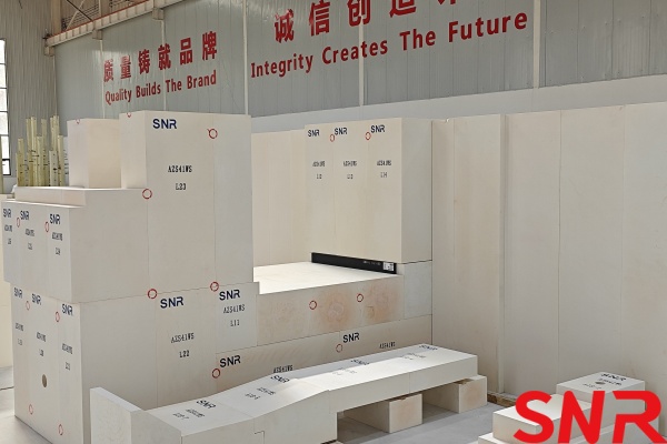
8.1 Configuration of Refractory Materials for Main Areas
Bottom Paving blocks
Melting zone: AZS 33# WS block, thickness 150 mm;
Step blocks, throat: AZS 41# WS block, thickness 150 mm;
Cooling zone, channels: Fused cast α-β alumina, thickness 75 mm.
Secondary layer paving blocks (melting zone): Sintered AZS block, thickness 100 mm.
Sidewall blocks
Doghouse, after bubblers: AZS 33# WS block, thickness 250 mm;
Other areas and corner blocks: AZS 41# WS block;
Throat: AZS 41# WS block, thickness 300 mm.
Channel areas: Fused cast α-β alumina, thickness 200 mm.
Melting Zone Breast Wall
Hook blocks: AZS 33# WS block;
Front of hot spot: AZS 33# PT block;
Behind hot spot: Fused cast α-β alumina-PT.
Melting Zone Rear Wall
Load-bearing crown: AZS 41# WS block;
Upper structure: Fused cast α-β alumina-PT.
Melting Zone Crown
Front of hot spot: Low-glass-phase AZS 33# PT block;
Behind hot spot: Fused cast α-β alumina-PT.
Horizontal flue passages and upper parts of vertical flues: AZS 33# PT block.
8.2 Total Refractory Weight
800 t/d oxy-fuel photovoltaic glass furnace: approx. 4700 t; 1000 t/d glass furnace: approx. 5000 t. The total refractory weight is less than half that of an air glass furnace of the same capacity, and total cost is slightly lower than an air glass furnace.
9. Process Control
9.1 Temperature Profile
Melting of the batch pile requires large amounts of heat. Considering heat absorption: batch pile, foam layer, and clean glass melt surface have different rates. If the batch pile absorption is taken as 1, foam absorption is 0.5, hot spot glass absorption is 0.4, and clean glass absorption is 0.3–0.4. Low temperature in the batch area can cause poor melting and fining, leading to bubbles that coalesce or form strings. The batch pile absorbs 1.5–2 times more heat from the flame space than from the lower glass layer, so the batch area temperature must be maintained. The ideal temperature profile is "mountain-shaped" with a pronounced hot spot and a clear, stable batch line. In air glass furnaces, the first few ports receive the maximum gas flow, and adjusting the front and rear branch damper heights ensures batch melting while maintaining the temperature difference between the hot spot and No.1 port.
The temperature profile for oxy-fuel glass furnaces is completely different. As mentioned, only front and rear flue pairs exist. If maximum gas flow is allocated to the batch area, high-temperature flue gases will take the shortest path to the exit, increasing energy consumption. In oxy-fuel glass furnaces, gas distribution is also "mountain-shaped," with the central combustion region receiving the maximum gas flow. This profile still maintains doghouse temperatures equivalent to air glass furnaces, while other process controls are generally similar to air glass furnaces.
10. Conclusion
(1) Large-scale oxy-fuel combustion photovoltaic glass furnaces have a simple structure, stable combustion, high thermal efficiency, and significantly improve the quality of ultra-thin, high-transmittance photovoltaic glass. With no crown or regenerator hot-repair work, operation and maintenance are simple, overall costs are lower, and market competitiveness is strong. They also positively respond to national goals of energy conservation, emission reduction, and green energy utilization. There is still room for improvement in their application to large photovoltaic glass furnaces, with broad prospects for extension to float glass and other fields.
(2) For large oxy-fuel glass furnaces, safety must be the top priority, with special attention to the fused cast crown. The design, application, and technology development of oxy-fuel glass furnaces above 1000 t/d require further research and discussion.
 I am Zoe. If you have any purchasing plans for fused cast AZS refractory blocks, please contact me.
[email protected]/ WhatsApp:+86 15670323812


 +86-18203976036