
Glass electric melting technology is often discussed in general terms, but in furnace engineering practice it actually comprises two distinctly different technical routes: all-electric melting, where electricity is the sole heat source for melting glass, and electric boosting, where electrodes supplement heat in a flame furnace. Both share the same physical principle—utilizing the electrical conductivity of high-temperature glass melt to generate Joule heat—but they differ fundamentally in applicable glass types, furnace structure, and operating logic. For furnace manufacturers, clarifying this distinction is the prerequisite for providing sound solutions to customers; and at the critical corrosion zones of both routes, refractory matching inevitably centers on fused-cast zirconia-alumina materials represented by AZS.
I. Same Principle, Two Routes
II. Applicability Boundaries and Engineering Reality of All-Electric Melting
III. Electric Boosting: The "Flexibility Regulator" of Flame Furnaces
IV. Refractories: The Hidden Determinant of Electric Furnace Campaign Life
Ⅴ. Conclusion
Glass is a poor conductor at room temperature, but as temperature rises, resistance gradually decreases, and molten glass acquires appreciable electrical conductivity. The core of electric melting technology is precisely to use the glass melt itself as the resistance heating element: current flows through electrodes immersed in the melt, generating Joule heat (W=I2RW=I2R), with heat transferring outward from within the glass rather than relying on external flame radiation.
All-electric melting takes this principle to its extreme. The furnace eliminates the combustion system entirely; all heat comes from electrodes, and the space above the glass melt surface is at very low temperature, forming what is known as a "cold top" structure. Batch materials cover the glass melt surface, forming a mixed batch layer approximately 20–30 cm thick, which serves both as thermal insulation and as a barrier suppressing the volatilization of volatile components. This structure enables all-electric furnaces to achieve thermal efficiency of over 80%, and in some cases even 85%. The process logic of vertical melting is clear: batch is charged from the top, sequentially undergoes silicate reactions, melting, and refining within a vertical depth of 1–3 meters, and finally flows out as qualified glass melt through the throat.
Electric boosting takes a different path. It acknowledges the heat transfer limitations of flame furnaces when melting refractory or dark glasses, and embeds electrodes as a "supplementary heating means" within the flame furnace system. Electrical input typically accounts for only 10%–30% of total heat, without changing the furnace‘s basic combustion architecture, yet it can increase melting capacity without furnace expansion. When electric boosting input accounts for about 10% of total heat, melting capacity can increase by approximately 20%; in some cases, electric boosting has contributed as much as 30% or even 50% of production.
The choice between the two routes is essentially a function of the customer‘s production portfolio and energy conditions. All-electric melting pursues "purity"—pure electrical energy, pure cold top, pure compositional stability; electric boosting pursues "flexibility"—within the existing flame furnace framework, achieving marginal improvements in output and quality with minimal modification.

II. Applicability Boundaries and Engineering Reality of All-Electric Melting
The advantages of all-electric melting lie in being "clean" and "stable." With no combustion exhaust, flue gas emissions are near zero, and the escape of volatile components such as fluorides and lead is significantly suppressed by the cold top layer. Melting occurs within the glass melt, with small temperature differences along the furnace depth, and glass melt uniformity and compositional stability superior to flame furnaces. These characteristics have established all-electric melting in the fields of refractory glass, volatile-containing glass, and specialty glass: borosilicate glass, high-alumina glass, glass-ceramics, lead crystal ware, optical glass, etc., are all typical application scenarios for all-electric melting.
A specific engineering case comes from Dianjiang, Chongqing. A pharmaceutical glass enterprise converted its natural gas horseshoe flame air-combustion furnace to an all-electric furnace, with three sets of electrodes configured at the upper, middle, and lower levels of the furnace for three-dimensional heating of the glass melt. After conversion, thermal utilization efficiency reached over 80%, NOx emission concentration dropped to approximately 0.024 mg/m³, and particulate matter concentration to approximately 256 μg/m³—essentially at ambient background levels; average energy consumption was approximately 4.4 t/d of standard coal equivalent, about 45% lower than the natural gas furnace. The glass-ceramics project in Fengyang, Anhui, likewise chose the all-electric route, building a new 120 t/d all-electric furnace to replace the original 70 t/d gas-fired furnace. The electric furnace‘s thermal efficiency increased from 50% (gas furnace) to over 65%, and by organizing production during off-peak nighttime electricity tariffs, preliminary estimates indicate annual energy and operating cost savings exceeding 3 million yuan per production line.
But the boundaries of all-electric melting are equally clear. Electricity cost is a hard constraint. The operating economics of all-electric melting depend heavily on local electricity prices; in high-tariff regions, ordinary soda-lime container glass is difficult to sustain. Moreover, all-electric furnace design is highly dependent on glass formulation—once resistivity, melting temperature, and refining characteristics are determined, the furnace‘s electrode arrangement and power configuration are essentially locked in. Patent literature shows that for borosilicate glass suitable for cold-top all-electric melting, the specific resistance at 1550°C must be controlled within a narrow range of 20–33 Ω·cm, and the ratio of total alkali and alkaline earth metals to the sum of acidic oxides must be maintained at 0.060–0.075. Outside this range, either conductivity is too high, causing current density to spiral out of control, or conductivity is too low, causing current to flow through stone materials. This means production flexibility is far inferior to flame furnaces, and furnace manufacturers must confirm the long-term glass portfolio plan with customers at the proposal stage.
III. Electric Boosting: The "Flexibility Regulator" of Flame Furnaces
The value of electric boosting lies not in replacing the flame, but in compensating for the flame‘s shortcomings. Flame radiation struggles to penetrate the surface layer of dark glass melt, resulting in slow heating and weak convection in the bottom glass melt; electric boosting heats from within, directly addressing this bottleneck. For difficult-to-melt types such as neutral borosilicate pharmaceutical glass and high-alumina electronic glass, flame heating is often insufficient, and electric boosting has become almost standard. China‘s first neutral borosilicate pharmaceutical glass production line using "oxy-fuel combustion + electric boosting" has been built, and simulation studies also show that electric boosting applied to high-alumina electronic glass furnaces can improve glass melt heating uniformity and flow, enhancing melting effectiveness and glass quality.
Another layer of value in electric boosting is production flexibility. When market orders fluctuate, adjusting output in a pure flame furnace means disrupting the balance of the entire thermal regime; electric boosting can quickly increase or decrease power within a certain range to achieve flexible production adjustment. References explicitly state that electric boosting "can adjust discharge rate according to different seasons, different time periods, and different sales volumes." But this flexibility has boundaries: the adjustment range is constrained by electrode power configuration and the thermal shock tolerance of refractories, and is not stepless arbitrary adjustment.
The risks of electric boosting are concentrated near the electrodes. Current density is highly concentrated at the electrode tips, and local temperature can far exceed the average glass melt temperature, accelerating electrode wear and corrosion of surrounding refractories. Electrode placement is therefore a critical design factor—mathematical simulation comparison for flat glass electric boosting shows that if boosting power is uniformly distributed in the batch charging area, the furnace bottom hot spot shifts forward, significantly altering the longitudinal flow pattern of the glass furnace, which is detrimental to melting and refining; a more reasonable approach is to distribute part of the power in the thermal barrier zone to maintain stability of the batch layer, circulation loop I, circulation loop II, and the production flow. Regarding electrode materials, molybdenum electrodes are most common but require water-cooling protection at high temperatures, and corrosion rate increases abruptly when current density exceeds 1.0 A/cm²; platinum electrodes are used for high-melting-point glasses such as TFT-LCD but are expensive and limited in power share.
IV. Refractories: The Hidden Determinant of Electric Furnace Campaign Life
Whether all-electric or electric boosting, refractories in the electrode zone endure harsh conditions uncommon in flame furnaces. Local high temperatures generated by current passing through the glass melt, enhanced glass melt convection, and changes in alkaline vapor concentration collectively accelerate corrosion of the sidewalls and refractories around the electrodes. Research presented at international glass conferences has explicitly noted that in scenarios where electrical energy is directly input to the glass melt through electrodes, alkali metal oxides in conventional AZS blocks reduce glass phase viscosity, potentially causing premature corrosion of refractories near the electrodes or glass defects (such as "exudation"). Therefore, AZS blocks in direct contact with electrodes must meet the special requirement of "high resistivity" to withstand the high temperatures generated by electrode heating and prevent early refractory failure caused by electrical short-circuiting.
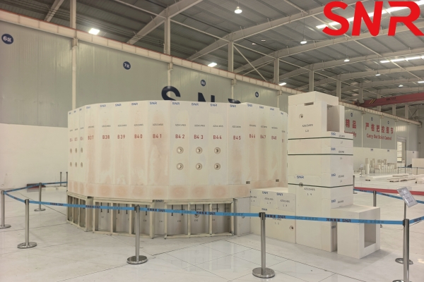
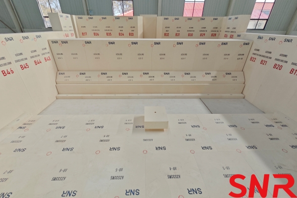
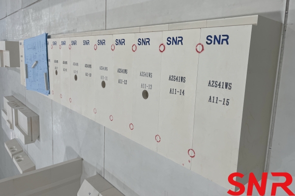
In the refractory system of glass furnaces, fused-cast zirconia-alumina blocks (AZS)are the primary choice for critical areas such as sidewalls, throats, and around electrodes. AZS blocks consist of α-corundum, baddeleyite, and glass phase; the eutectic structure of baddeleyite and corundum gives them good resistance to glass melt corrosion, and the glass phase, after high-temperature corrosion, forms a high-viscosity layer dissolved with ZrO₂ that remains on the block surface as protection. By ZrO₂ content, AZS is classified into 33#, 36#, 41#, etc. AZS33# has a ZrO₂ content of 32%–34%, suitable for areas with moderate corrosion such as upper furnace structures and working end sidewalls; AZS36# raises ZrO₂ content to 35%–40% with correspondingly lower glass phase, suitable for areas with faster glass melt flow or higher temperatures; AZS41# has a ZrO₂ content of 40%–42% and is the most corrosion-resistant grade in the AZS series, used for hot spot sidewalls, batch charging corner, throat, dams, and critical areas of all-electric furnaces.
For electric melting furnaces, AZS41# or higher-zirconia materials are often a reasonable starting point for electrode surroundings and throats. But selection cannot stop at the grade designation. Physical performance indicators are equally critical: AZS41 requires bulk density ≥3.90 g/cm³ and apparent porosity ≤1.3%; low porosity means glass melt is less able to penetrate into the block interior. When electric boosting intensity increases, furnace bottom glass temperature may rise significantly, and the direct corrosion rate of refractories increases accordingly; the electrode block area also faces the risk of glass melt penetrating along block joints and "drilling upward." Industry experience shows that furnace bottom paving blocks, joints, and sealing layers must be combined into a sealed integral whole, using fused-cast AZS ramming mix with essentially the same crystalline phase as the paving blocks to fill joints tightly, so that blocks, joints, and sealing layer sinter into a composite layer at high temperature, effectively preventing glass melt seepage. This means that for furnaces with high electric boosting ratios, the furnace bottom structure design must consider AZS material selection and masonry technology as an integrated solution.
For furnace manufacturers, when recommending electric melting solutions to customers, presenting refractory selection and electrode power configuration as an integrated solution is more persuasive than discussing the furnace or the blocks separately. After all, the campaign life and operating economics of electric melting furnaces ultimately rest on those blocks that directly bear the combined action of current and glass melt. If AZS selection for the electrode zone is downgraded based on average operating conditions, short-term block cost savings may come at the expense of shortened campaign life and increased hot repair frequency in the long run.
Glass electric melting technology is not a single solution, but rather two parallel routes: all-electric melting and electric boosting. Both share the physical principle of "using the glass melt itself as the resistance heating element," yet they are clearly distinct in applicable glass types, furnace structure, and operating logic. All-electric melting uses electricity as the sole heat source; its cold-top structure delivers thermal efficiency above 80% and near-zero flue gas emissions, with clear advantages in borosilicate pharmaceutical glass, high-alumina electronic glass, glass-ceramics, and lead/fluorine-containing volatile glasses. However, its economics are hard-constrained by electricity prices, and furnace design is deeply bound to glass formulation, limiting production flexibility. Electric boosting, by contrast, is positioned as the flexibility regulator of flame furnaces, using a 10%–30% supplementary heating ratio to achieve approximately 20% output increase without furnace expansion, improve the quality of dark and refractory glasses, and flexibly adjust discharge rate—at the cost of local overheating near electrodes, dependence on glass electrical conductivity, and sensitivity to electricity prices.
The engineering success of both routes ultimately rests on the refractories in the electrode zone and throat. Fused cast AZS blocks are the primary choice for these critical areas: AZS33# is suitable for moderately corrosive locations, AZS36# handles areas with faster flow or higher temperatures, and AZS41#, with the highest corrosion resistance, serves hot spot sidewalls, throats, dams, and critical areas of all-electric furnaces. For electric melting furnaces, selection cannot stop at the grade designation—electrode contact areas require attention to high-resistivity requirements, the furnace bottom must be designed with blocks, ramming mix, and masonry technology as a sealed integral whole, and under high electric boosting ratios, allowances should be made based on the most severe corrosion conditions rather than downgraded configuration based on average operating conditions.
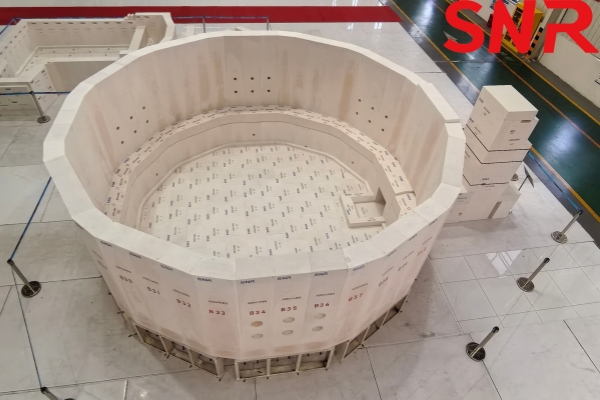
Henan SNR Refractory Co., Ltd. has been specializing in the production of fused cast AZS blocks for more than 25 years. We use high-quality raw materials and advanced fusion and casting technology and equipment to provide customers with high-quality products. From raw material procurement to finished product delivery, every step is strictly quality inspected to ensure that every indicator meets the standards, so you can use it with confidence.
Should you have any inquiries or specific requirements, our team is ready to provide professional support and tailored solutions.
 Contact Information:
Web: www.snr-azs.com
Email: [email protected]


 +86-18203976036
